A socket and connector assembly

A connector assembly and jack contact technology, which is applied to the parts, connections, and contact parts of the connecting device, can solve the problems of inability to achieve conductive connection, occupying space for plugging, damage and deformation of jacks, etc., so as to improve the sealing effect. Waterproof effect, improve sealing water resistance, reduce plug resistance effect

Active Publication Date: 2018-01-16
CHINA AVIATION OPTICAL-ELECTRICAL TECH CO LTD
View PDF7 Cites 0 Cited by
  • Summary
  • Abstract
  • Description
  • Claims
  • Application Information

AI Technical Summary

Problems solved by technology

[0003] The Chinese invention patent with the publication number CN101106230A and the announcement date of January 16, 2008 discloses a plug-in sealing structure for underwater electrical connector contacts. A drainage groove is set between the insulating sleeve on the top and the socket insulator, that is, the mating surface on the socket insulator to achieve the purpose of draining the water between the two when the plug and socket are inserted, although such a mating sealing structure can Drain the accumulated water between the plug and the socket, but there is no way to discharge the water that enters the socket socket contact before insertion, so that the water in the socket contact occupies a certain insertion space, resulting in resistance to insertion Very large, it is difficult to insert into the insertion position, that is, the insertion end of the pin contact is located at the bottom of the socket of the socket contact, which seriously affects the use of the connector, and the forced insertion will easily cause the pin The plug-in end of the contact or the socket of the socket contact is damaged and deformed, and even the seal fails and the conductive connection cannot be realized, and it cannot be used normally

Method used


Image

  • A socket and connector assembly
  • A socket and connector assembly
  • A socket and connector assembly

Examples


Embodiment Construction

[0023] The connector assembly of the present invention will be described in detail below in conjunction with the accompanying drawings:

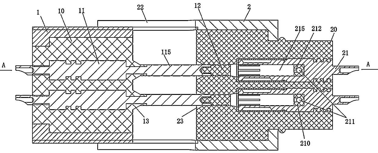
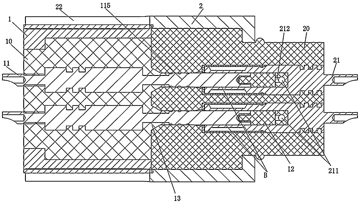
[0024] Embodiment 1 of the connector assembly of the present invention: as Figure 1-3 As shown, it includes a plug and a socket, wherein the plug includes a plug housing 1, the plug housing 1 is a cylindrical shape extending left and right, its outer peripheral surface is provided with connecting threads, and a plug insulator 10 is fixed inside, and the plug insulator 10 is fixed inside. The pin contact 11, the pin contact 11 extends in the left and right directions, the overhanging section of the pin contact 11 protruding from the right side of the plug insulator 10 is the plug end 115, and the right end of the plug end 115 is provided with a sealing insulation 12.

[0025] Socket comprises socket shell 2, and socket shell 2 is also the cylindrical shape that extends left and right, and socket insulator 20 is fixedly arranged in socket sh...


PUM


Abstract

The invention provides a socket and a connector assembly. The socket includes a socket insulator and a socket contact provided on the socket insulator. The socket contact has a socket, and the socket contact is provided with a socket connecting the socket The through channel outside the socket contact, the through channel is pierced with a drainage channel that is insulated and cooperates with the socket contact to discharge the water in the socket during the insertion process, and the drainage channel has a channel that communicates with the socket The inner end is open, and the periphery of the inner end opening of the passage has a sealing matching surface of the drainage passage. When the plug-in end of the pin contact extends into the socket, the water in the socket can be directly discharged out of the socket through the drainage channel, which will not bring insertion resistance to the plug-in end of the pin. When the component is pulled out from the socket of the socket contact, the water can reversely flow from the outside of the socket to the socket of the socket contact through the drainage channel, so that the pressure on the left and right ends of the pin contact is balanced, and the plug-in and pull-out comparison Save effort.

Description

technical field [0001] The invention relates to a conductive connection device, in particular to a socket and a connector assembly. Background technique [0002] With the development of submarine power transmission, the application of underwater connectors is becoming more and more extensive, and its role is becoming more and more important. The main technical problem of the underwater electrical connector is how to ensure the conductive seal, especially the problem of ensuring that there will be no water accumulation between the plug and the socket during the insertion process. [0003] The Chinese invention patent with the publication number CN101106230A and the announcement date of January 16, 2008 discloses a plug-in sealing structure for underwater electrical connector contacts. A drainage groove is set between the insulating sleeve on the top and the socket insulator, that is, the mating surface on the socket insulator to achieve the purpose of draining the water betw...

Claims


Application Information

Patent Timeline
Patent Type & Authority Patents(China)
IPC IPC(8): H01R13/502H01R13/02H01R13/523
Inventor 李思行张磊张晓光孙晓龙
Owner CHINA AVIATION OPTICAL-ELECTRICAL TECH CO LTD
Why Eureka
Try Eureka