Electrical equipment monitoring method and device

A technology for power equipment and monitoring devices, which is applied in the field of power equipment monitoring methods and monitoring devices, can solve problems such as difficult deployment, large deployment space, and data scale expansion, and achieve convenient and fast display operations, increase communication speed, and relieve memory pressure. Effect

Inactive Publication Date: 2015-11-11
SHANDONG LUNENG SOFTWARE TECH
View PDF3 Cites 6 Cited by
  • Summary
  • Abstract
  • Description
  • Claims
  • Application Information

AI Technical Summary

Problems solved by technology

In actual monitoring scenarios, due to the large amount of monitoring data of power equipment, the rapid expansion of data scale, and the development requirements of comprehensive integrated analysis and processing with the advancement of science and technology, traditional databases can no longer meet the requirements of storage and integrated analysis and processing.
[0003] With the rapid development of computer technology, the data in various industries has grown rapidly, the amount of data has become larger and larger, the types have become more and more, and the data structure has become more complex. The traditional database is not only independent of each device, but also requires a large There are disadvantages such as difficult deployment and high cost, which cannot meet the general requirements of users
The emergence and development of big data all-in-one machines and their databases has become a new development trend. However, there are currently no power equipment monitoring methods and monitoring devices designed and used specifically for the power industry to meet big data processing and storage.

Method used


Image

  • Electrical equipment monitoring method and device
  • Electrical equipment monitoring method and device
  • Electrical equipment monitoring method and device

Examples


Embodiment Construction

[0037] The concrete implementation of the present invention is described in detail below, it is necessary to point out here that the following implementation is only used for further description of the present invention, and can not be interpreted as limiting the protection scope of the present invention. Some non-essential improvements and adjustments still belong to the protection scope of the present invention.

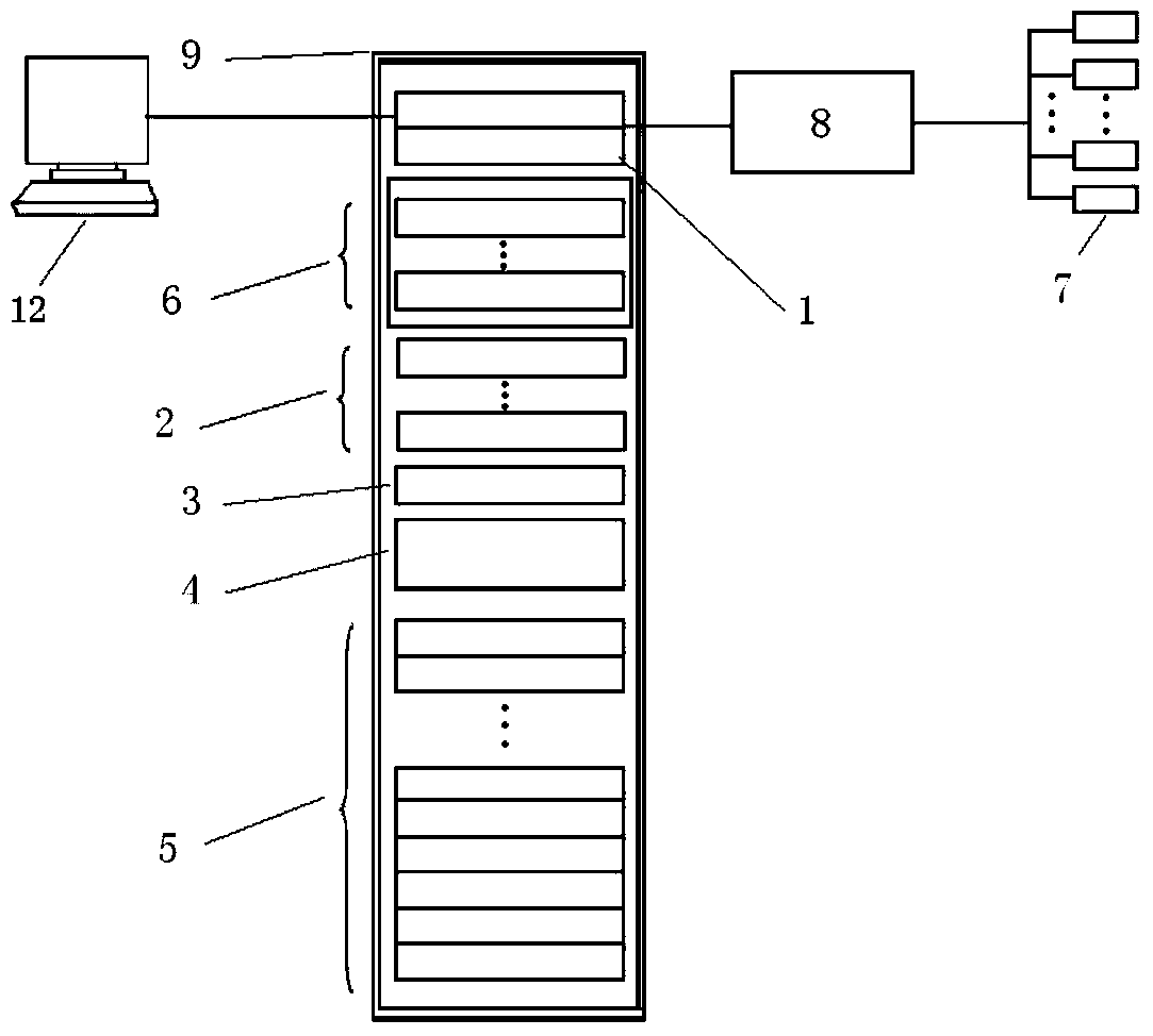
[0038] The invention provides a method for monitoring electric equipment, comprising the following steps:

[0039] (1) initialization, parameter setting is carried out to each component in the monitoring device;

[0040] (2) Use power analysis tools to establish power business analysis models;

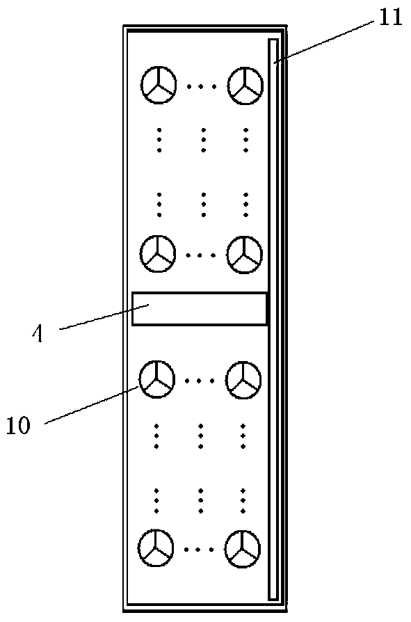
[0041] (3) Use the temperature sensor to measure the temperature in the cabinet in real time, and control the output power of the fan in stages according to the temperature in the cabinet;

[0042] (4) Obtain the measurement point information of the substation equipment i...


PUM


Abstract

The invention provides an electrical equipment monitoring method and a monitoring device thereof. The electrical equipment monitoring method comprises the following steps of: initializing; setting parameters; establishing an electrical business analysis model; controlling output power of a fan by grades; acquiring measuring point information of power transformation equipment in real time; and transmitting the acquired measuring point information of the power transformation equipment to a real-time database to be packaged and stored; and transmitting inquiry, accounting, analysis and / or processing operation requests to the electrical equipment monitoring device according to the request of a user; and displaying to the user in real time after visualized processing. The electrical equipment monitoring method is real-time and effective; the equipment is high in integration level and availability, good in expansibility, and stable in system performance, as well as simple and convenient to operate.

Description

technical field [0001] The invention relates to the application field of monitoring and analysis of electric equipment, in particular to a monitoring method and a monitoring device for electric equipment. Background technique [0002] At present, in order to ensure the safe, stable and efficient operation of the power grid, the state monitoring of substation equipment is usually carried out, and the monitored equipment measurement point data is stored in the real-time database, and the data in the real-time database is periodically transferred to the historical database. Equipment failure early warning and monitoring provide analysis data. In actual monitoring scenarios, due to the large amount of monitoring data of electric power equipment, the rapid expansion of data scale, and the development requirements of comprehensive integrated analysis and processing with the advancement of science and technology, traditional databases can no longer meet the requirements of storage ...

Claims


Application Information

Patent Timeline
IPC IPC(8): G06F17/30G06Q50/06
CPCG06F16/21G06F16/2379G06Q50/06
Inventor 丁书耕王震陈亮王复强
Owner SHANDONG LUNENG SOFTWARE TECH
Why Eureka
Try Eureka