
Method and device for measuring electromagnetic emission characteristics of electronic device on site

A technology of emission characteristics and on-site testing, which is applied in the direction of measuring devices, measuring electricity, and measuring electrical variables, etc., can solve the problems of not involving electromagnetic compatibility on-site testing, being unable to use actual testing, not having shielding, and filtering environments, etc.

Active Publication Date: 2015-11-11
XIDIAN UNIV
View PDF4 Cites 15 Cited by
  • Summary
  • Abstract
  • Description
  • Claims
  • Application Information

AI Technical Summary

Problems solved by technology

[0004] Due to the lack of ideal shielding and filtering environment for electromagnetic compatibility field testing, there are both signals generated by the equipment itself and environmental noise signals in the environment, which seriously affects the accuracy of the test and increases the difficulty of fault diagnosis.
At present, the only standard on EMC field testing in my country, YDT1633-2007 "Electromagnetic Compatibility Field Test Method" stipulates the performance criteria, disturbance and immunity measurement methods of equipment-level products during EMC field testing, but does not involve complex On-site EMC testing in the electromagnetic environment and networked working conditions, not to mention the processing method of test data and detailed requirements for EMC
The virtual darkroom theory uses dual-channel receiver measurement and adaptive noise cancellation technology to test the radiation emission of the device under test in a normal environment. Since the distance between the interference source and the sensitive device is very close during the actual test, it cannot meet the theoretical requirements of this method. The required test distance above, so it cannot be used for actual testing

Method used


Image

  • Method and device for measuring electromagnetic emission characteristics of electronic device on site
  • Method and device for measuring electromagnetic emission characteristics of electronic device on site
  • Method and device for measuring electromagnetic emission characteristics of electronic device on site

Examples


Embodiment Construction

[0061] Such as Figure 4-7 As shown, a field test device for electromagnetic emission characteristics of electronic equipment at least includes a portable biconical antenna 2, a current caliper 3, a near-field probe 4, an active preamplifier 5, a receiver 6, and a coaxial shielded cable 7, The portable biconical antenna 2 is electrically connected to the receiver 6 through a coaxial shielded cable 7, and the receiver 6 is electrically connected to the computing unit 8 through an interface line.

[0062] Such as Figure 5 As shown, during the radiation emission test, the portable biconical antenna 2 is placed at a distance of 1m from the device under test 1, and the portable biconical antenna 2 is connected to the receiver 8 through a coaxial shielded cable 7, and the center of the portable biconical antenna 2 Align with the center of the device under test 1.

[0063] Such as Figure 6 As shown, during the conducted emission test, the current caliper 3 is clamped on a cable ...


PUM


Abstract

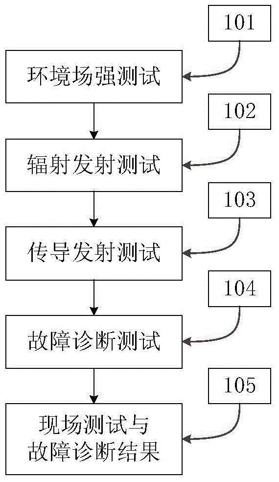
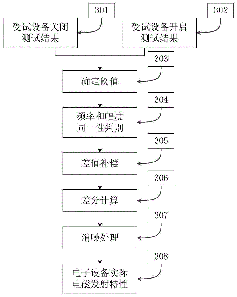
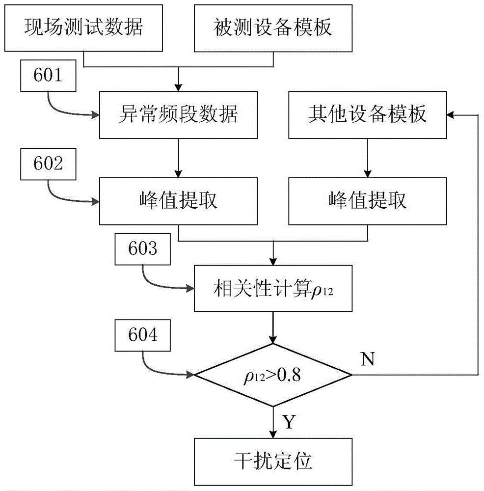
The invention discloses a method and a device for measuring electromagnetic emission characteristics of an electronic device on site, comprising steps of environment field intensity test, radiation emission test, conduction emission test, and fault diagnosis test. The environment field intensity test includes the step of performing the test on the electromagnetic environment of the device working site to determine the environment permanent signal and whether newly increased abnormal signals exist; the radiation emission test comprises steps of testing the radiation emission in the frequency range from 10kHz to 3GHz through a portable biconical antenna, performing processing on test data through an environment rejecting algorithm and obtaining practical electromagnetic emission characteristics of a tested device; the conduction emission test includes steps of testing the conduction emission in the frequency range of 25Hz to 10MHz through a current caliper and testing the coupling between lines in the frequency range of the 25Hz to 250MHz; the fault diagnosis test includes steps of respectively choosing near-field probes with various precision according to the electromagnetic emission characteristics of the tested device,and further determining the electromagnetic emission characteristics of a particular part. The method disclosed by the invention also comprises a step of performing correlation calculation on the on-site test data abnormal frequency band and other device templates to obtain the results of the on-site test and the fault diagnosis.

Description

technical field [0001] The invention belongs to the field of electromagnetic compatibility testing, in particular to a field testing method and device for electromagnetic emission characteristics of electronic equipment. Background technique [0002] With the rapid development of electronic technology, the cable layout of the system is complicated, there are many components, and the operating frequency and transmission rate increase, which leads to the increasingly prominent electromagnetic compatibility problems of electronic systems. Due to the limitation of the system volume and the requirement of real-time testing, the electromagnetic compatibility test cannot be carried out in the shielded room, and for the equipment under test, the electromagnetic emission characteristics of the actual working state and the laboratory state are very different. The most obvious difference is that the former is in the actual working environment, and the equipment is in the working state ...

Claims


Application Information

Patent Timeline
Patent Type & Authority Applications(China)
IPC IPC(8): G01R31/00
Inventor 许清琳邱扬田锦张建国王森许社教
Owner XIDIAN UNIV
Learn More