
Multimodal ultrasonic Lamb wave complex defect tomography method

A tomography, complex defect technology, applied in the direction of using sonic/ultrasonic/infrasonic waves to analyze solids, etc., can solve problems such as increasing difficulty and error, inability to accurately estimate specific dimensions and contours, affecting imaging results, etc. The effect of reducing the influence of noise, improving recognition efficiency and imaging accuracy, and broad application prospects

Inactive Publication Date: 2015-11-11
TSINGHUA UNIV
View PDF5 Cites 9 Cited by
  • Summary
  • Abstract
  • Description
  • Claims
  • Application Information

AI Technical Summary

Problems solved by technology

However, when encountering complex defects with gradual depth changes, more noise will be superimposed on the obtained slowness distribution, and the slowness changes caused by defects will be covered by noise to a certain extent, which will make the slowness distribution from The difficulty and error in extracting defect feature information from the slowness distribution map will increase, which will affect the imaging results
The Chinese patent document discloses a "ray-tracing ultrasonic Lamb wave defect tomography method". This technology involves an ultrasonic Lamb wave online detection method for aluminum plate defects, using an EMAT (Electromagnetic Acoustic Transducer) array to send and receive a single Lamb wave , by combining the iterative reconstruction algorithm and the ray tracing correction algorithm to reconstruct the tomographic image, the comprehensive detection and defect analysis of single round hole defects in aluminum plates can be realized more accurately, but this technology is limited to regular defects with uniform depth, and the depth change The specific size and outline of complex defects cannot be estimated very accurately, and there are certain limitations

Method used


Image

  • Multimodal ultrasonic Lamb wave complex defect tomography method
  • Multimodal ultrasonic Lamb wave complex defect tomography method
  • Multimodal ultrasonic Lamb wave complex defect tomography method

Examples


Embodiment Construction

[0028] Embodiments of the present invention are described in detail below, examples of which are shown in the drawings, wherein the same or similar reference numerals designate the same or similar elements or elements having the same or similar functions throughout. The embodiments described below by referring to the figures are exemplary only for explaining the present invention and should not be construed as limiting the present invention.

[0029] In describing the present invention, it should be understood that the terms "center", "longitudinal", "transverse", "upper", "lower", "front", "rear", "left", "right", " The orientations or positional relationships indicated by "vertical", "horizontal", "top", "bottom", "inner" and "outer" are based on the orientations or positional relationships shown in the drawings, and are only for the convenience of describing the present invention and Simplified descriptions, rather than indicating or implying that the device or element refe...


PUM

PropertyMeasurementUnit
diameteraaaaaaaaaa

Abstract

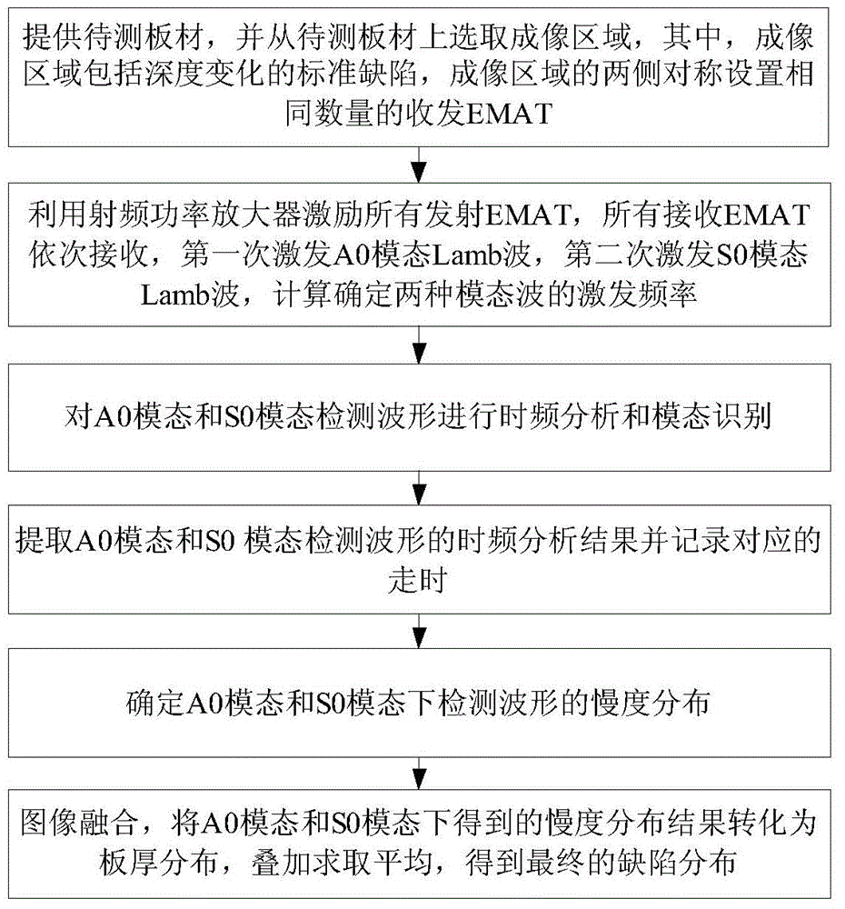
The invention provides a multimodal ultrasonic Lamb wave complex defect tomography method. The method comprises the following steps: presetting a sensitivity threshold THs and a sensitivity dead zone dz, and calculating to obtain the appropriate working frequencies of Lamb waves with A0 and S0 modals; carrying out A0 wave cross-hole tomography and S0 wave cross-hole tomography under respective working frequency conditions by respectively using A0 wave EMAT array and S0 wave EMAT array; and carrying out image fusion, and organically combining two results to obtain a final defect image reconstruction result. The method fully uses different sensitive areas of the Lamb waves with different modals to carry out complementation of the sensitive areas, so the method has the advantages of enlargement of the integral sensitive area of tomography, reduction of influences of noises, effective reduction of the difficulty of extraction of defect characteristic information from a slowness distribution map, improvement of the identification efficiency and imaging precision of complex defects, and wide application prospect.

Description

technical field [0001] The invention relates to a multi-mode ultrasonic Lamb wave complex defect tomography method, which belongs to the technical field of non-destructive testing. Background technique [0002] The specific information such as the outline and size of the defect can be obtained quickly and effectively by using the ultrasonic Lamb wave defect tomography technology. This technology inherits many advantages of traditional ultrasonic Lamb wave detection. Lamb wave travel time (Time-of-flight, TOF, refers to the propagation time of Lamb wave between the transmitting and receiving transducer pairs) cross-aperture tomography technology, using linear transducer array for fan beam projection and imaging, is a kind of An efficient and fast tomography method based on an iterative method. The direct output of this imaging method is the distribution of Lamb wave slowness (reciprocal of velocity), which reflects the distribution of defects through the variation of slowne...

Claims


Application Information

Patent Timeline
Patent Type & Authority Applications(China)
IPC IPC(8): G01N29/06
Inventor 黄松岭赵伟王珅魏争李世松
Owner TSINGHUA UNIV
Learn More