
Quantum correlated autocollimator and angle measurement method thereof

An autocollimator and quantum correlation technology, which is applied in the field of measurement, can solve the problems of mutual restriction between the range of angle measurement and the accuracy of angle measurement, the miniaturization of the autocollimator, and the large range of angle measurement, so as to eliminate the influence of atmospheric turbulence, The effect of reducing cost and volume, and high technology maturity

Active Publication Date: 2015-11-11
BEIJING INST OF AEROSPACE CONTROL DEVICES
View PDF5 Cites 5 Cited by
  • Summary
  • Abstract
  • Description
  • Claims
  • Application Information

AI Technical Summary

Problems solved by technology

[0003] The technical problem solved by the present invention is: to overcome the disadvantages of the existing classical autocollimator, such as the large volume, the mutual restriction between the angle measurement range and the angle measurement accuracy, and propose a quantum correlation autocollimator and angle measurement method, which solves the problem of the automatic Problems of collimator miniaturization, large angle measurement range and high angle measurement accuracy

Method used


Image

  • Quantum correlated autocollimator and angle measurement method thereof
  • Quantum correlated autocollimator and angle measurement method thereof
  • Quantum correlated autocollimator and angle measurement method thereof

Examples


Embodiment Construction

[0029] The present invention will be described in detail below in conjunction with the accompanying drawings and specific embodiments.

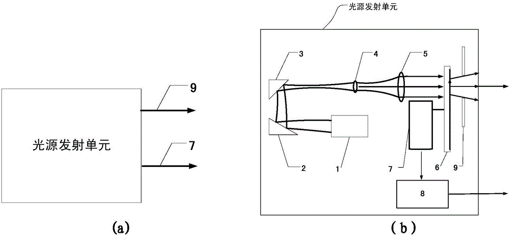
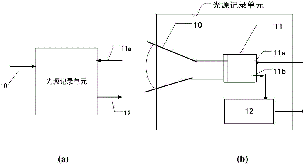
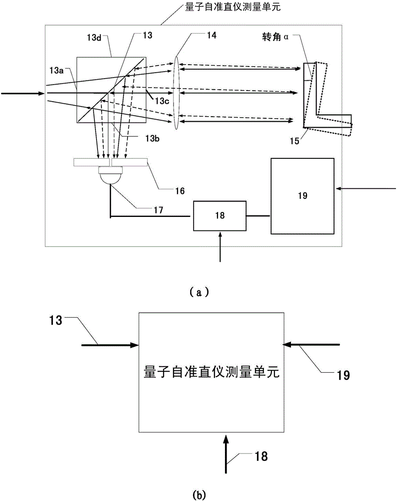
[0030] The invention discloses a quantum correlation autocollimator, such as figure 1 (a) and (b), figure 2 (a) and (b), as shown in (a) and (b) of Figure (3), include: a light source emitting unit, a light source recording unit, and a quantum autocollimator measuring unit;

[0031] The light source emitting unit includes a laser 1, a first reflector 2, a second reflector 3, a first lens 4, a second lens 5, a control unit 8, a stepping motor 7, a ground glass 6 and a first aperture 9;

[0032] The light source recording unit includes: a zoom lens 10, an industrial camera 11 and an image acquisition and storage unit 12;

[0033] Quantum autocollimator measurement unit includes: 50:50 beam splitter 13, third lens 14, third mirror 15, second diaphragm 16, photodetector 17, data acquisition card 18, data processing and display module 19 ;

...


PUM


Abstract

The invention relates to a quantum correlated autocollimator and an angle measurement method thereof. A stepping motor and pulse modulation control are used to code an optical field, an industrial camera and a zoom lens shoot a series of images, which is magnified or reduced for omega times, of the optical field, and the images are stored in a storage unit for later use according to the time sequence. An aperture diaphragm and a single-pixel photoelectric detector are used to replace an array camera part of a classic autocollimator, collected photoelectric detection signals are correlated and calculated with the series of images shot by the industrial camera, and a calculation result includes the coordinate of the imaging position of the aperture diaphragm. Reflectors are rotated, and measurement is carried out repeatedly to obtain two coordinates of the imaging position of the aperture diaphragm, one coordinate is reduced by the other coordinate, corner information can be obtained according to the classic autocollimator information, and thus, angle measurement is completed. The disadvantages that the classic autocollimator is large and the range and the precision of angle measurement restrict each other are overcome, and the autocollimator of the invention is small, wide in measuring range and high in measuring precision.

Description

technical field [0001] The invention relates to a quantum correlation autocollimator and an angle measurement method, belonging to the field of measurement. Background technique [0002] Classical autocollimator products generally use a line array or area array industrial camera and an imaging lens group to measure the rotation angle of the mirror, so as to achieve the measurement and calibration of the flatness or collimation of the device. At present, the miniaturization and portability of classical autocollimators are mainly limited by their basic principles. On the one hand, the larger the focal length f of the lens group, the higher the angle measurement accuracy, but the corresponding maximum angle measurement range becomes smaller. On the other hand, the larger the focal length f of the lens group requires the larger the volume of the autocollimator. Therefore, the angle measurement accuracy, angle measurement range and design volume of the classical autocollimator ...

Claims


Application Information

Patent Timeline
IPC IPC(8): G01B11/26G02B27/30
Inventor 李明飞霍娟杨然张安宁刘院省莫小范赵连洁
Owner BEIJING INST OF AEROSPACE CONTROL DEVICES
Learn More