Automatic decoking combustor for burning biomass fuel
A biomass fuel and combustion chamber technology, which is applied in combustion methods, combustion equipment, mobile grate and other directions, can solve the problems of blocking the ventilation holes of the grate plate, etc., and achieves reduced friction, fast automatic coking removal efficiency and simple structure. Effect
- Summary
- Abstract
- Description
- Claims
- Application Information
AI Technical Summary
Problems solved by technology
Method used
Image
Examples
Embodiment 1
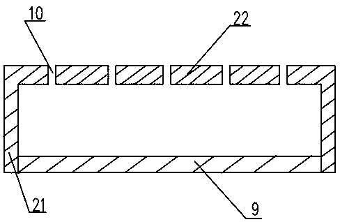
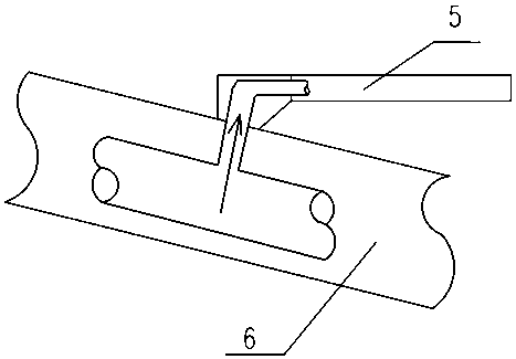
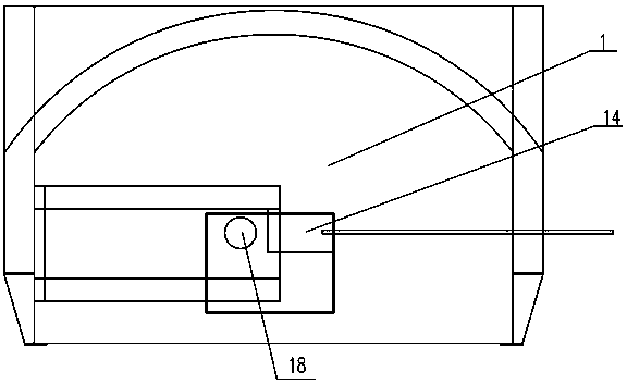
[0042] Such as Figure 1 to Figure 6 As shown, an automatic decoking combustion chamber for burning biomass fuel is used in conjunction with biomass burners, figure 1 The connecting flange 27 on the far right side can be connected to other related equipment. In this embodiment, the designed steam production rate is 6 tons / hour, and the burning fuel per hour is 900kg. It is a relatively large burner, including the grate located in the furnace 1 The grate plate includes a movable grate plate 5 and a fixed grate plate 4 fixed in the furnace. The movable grate plate 5 is frictionally matched with the fixed grate plate 4. The main bodies of the fixed grate plate 4 and the movable grate plate 5 are heat-resistant The groove-shaped metal cover plate made of metal material is made of heat-resistant cast iron in this embodiment. The groove-shaped cover plate is arranged in the furnace 1 poured by refractory concrete layer in the way of groove undercut. The groove-shaped cover plate In...
Embodiment 2
[0057] The difference between this embodiment and Embodiment 1 is that a water circulation system is arranged above the furnace of the combustion chamber, and it is used in a biomass boiler. This embodiment is designed to produce 2 tons of steam and burn 300 kg of fuel per hour, which is a relatively small boiler. The groove of its fire grate plate is not provided with sealing plate 9, and the plate leg 21 of fire grate plate is directly in frictional contact with the plate surface 22 of next fire grate plate, and fire grate plate comprises six fixed grate plates 4 and five movable ones. Grate plate 5, the vent hole 10 diameter of groove type fire grate plate is 7mm, is oblique hole, and the biomass fuel diameter that this combustion chamber selects is 9mm. The mobile bracket 6 is a rod type, and all the fixed grate plates 4 and the movable grate plates 5 share an air supply system, which includes an integral bellows arranged under all the grate plates and communicated with the...
Embodiment 3
[0059] The difference between this embodiment and Embodiment 1 is that a water circulation system is arranged above the furnace of the combustion chamber, and it is used in a biomass boiler. The design steam gas production is 1 ton, and the fuel can burn 150 kg per hour. It is a small boiler. The grate plate includes Four fixed grate plates 4 and three movable grate plates 5, the vent hole 10 diameter of groove type fire grate plate is 5mm, is oblique hole, and the biomass fuel diameter that this combustor selects is 8mm. The air supply pipeline of the movable grate plate 5 is the same as that of Embodiment 1. Each fixed grate plate 4 is only designed to supply air on one side, which is a one-way side air supply. The main pipe 17 is arranged on the lower side of the fixed grate plate 4, and the fixed grate plate There is no need to set a longitudinal cavity partition plate in the plate 4, there is only one fan, the air supply duct of the movable grate plate 5 is connected with ...
PUM
 Abstract
Description
Claims
Application Information
 - R&D
- Intellectual Property
- Life Sciences
- Materials
- Tech Scout
- Unparalleled Data Quality
- Higher Quality Content
- 60% Fewer Hallucinations
Browse by: Latest US Patents, China's latest patents, Technical Efficacy Thesaurus, Application Domain, Technology Topic, Popular Technical Reports.
© 2025 PatSnap. All rights reserved.Legal|Privacy policy|Modern Slavery Act Transparency Statement|Sitemap|About US| Contact US: help@patsnap.com


