Method for operating hydraulic brake equipment

A technology of hydraulic braking and equipment, applied in the direction of brakes, brake transmission devices, braking action starting devices, etc., can solve problems such as noise

Active Publication Date: 2019-07-16
ROBERT BOSCH GMBH
View PDF5 Cites 0 Cited by
  • Summary
  • Abstract
  • Description
  • Claims
  • Application Information

AI Technical Summary

Problems solved by technology

Activation of the return pump causes noise generation

Method used


Image

  • Method for operating hydraulic brake equipment
  • Method for operating hydraulic brake equipment
  • Method for operating hydraulic brake equipment

Examples


Embodiment Construction

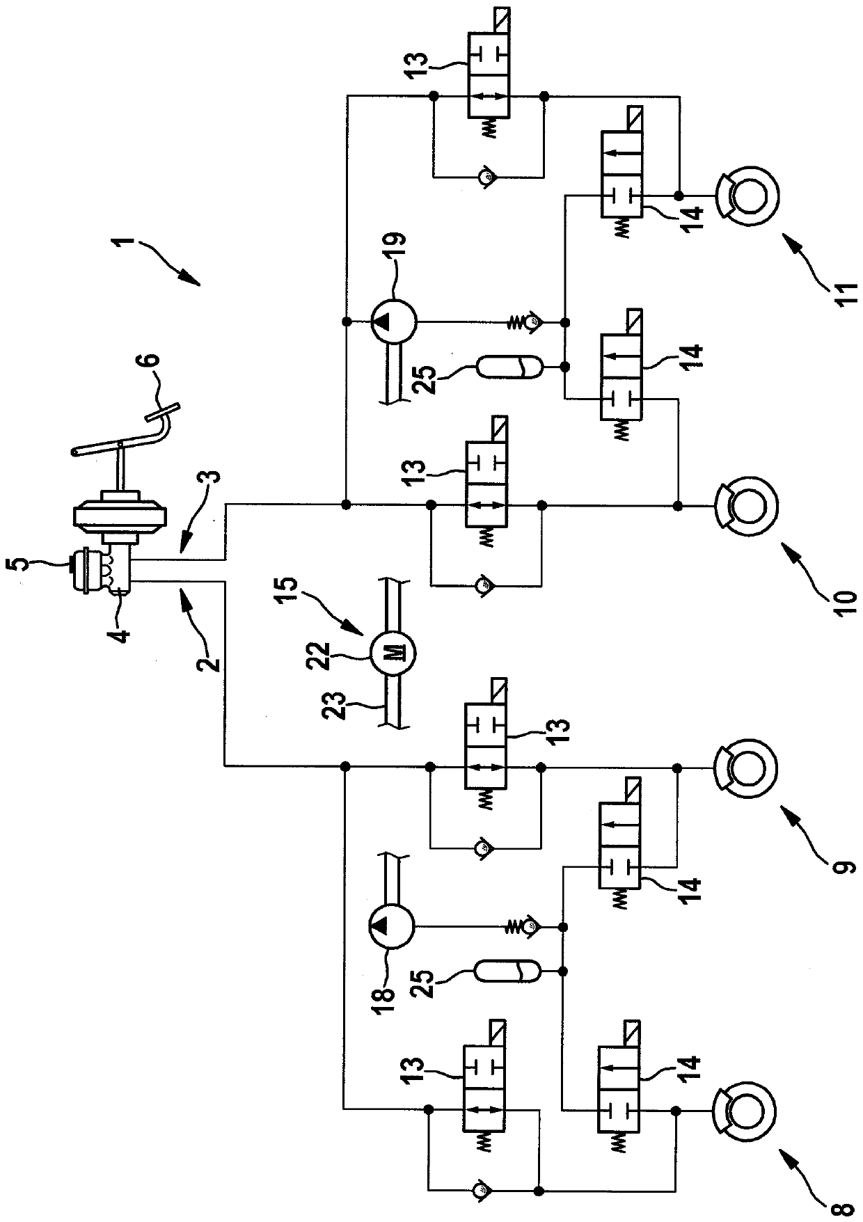
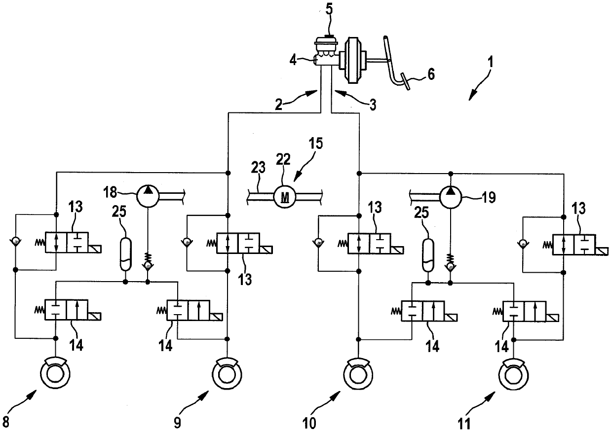
[0018] in accordance with figure 1 The hydraulic brake system shown in the hydraulic circuit diagram in the brake system 1 has a first brake circuit 2 and a second brake circuit 3 for each of the two wheel brake units 8, 9, 10, 11 Supply hydraulic brake fluid. The brake circuit assignment is, for example, diagonal, so that each brake circuit 2 , 3 is provided with a wheel brake unit on a front wheel and a rear wheel.

[0019] The two brake circuits 2 , 3 are connected to a common master brake cylinder 4 , which is supplied with brake fluid via a brake fluid reservoir 5 . Master brake cylinder 4 is actuated by the driver via brake pedal 6 , the pedal travel applied by the driver can be measured by a pedal travel sensor.

[0020] In each brake circuit 2, 3 there is an inlet valve 13 which is open without current (normally open) and is assigned a non-return valve which can be connected from the wheel brake unit in the direction of the master brake cylinder Upstream.

[0021] ...


PUM


Abstract

In a method for actuating a hydraulic braking system, a hydraulic fluid is temporarily stored in a storage chamber when the antilocking system is activated. An additional hydraulic buffer volume of the storage chamber increases as the vehicle speed decreases.

Description

technical field [0001] The invention relates to a method for operating a hydraulic brake system with an antilock braking system in a motor vehicle. Background technique [0002] Hydraulic brake systems are known which have an integrated anti-lock braking system for preventing the wheels from locking up in the event of a heavy braking operation. The brake system has one or more hydraulically actuatable wheel brake units in a brake circuit, the hydraulic fluid being controlled via inlet valves and outlet valves of the wheel brake units. The anti-lock braking system consists of an electrically actuatable return pump and a reservoir integrated in the brake circuit for receiving hydraulic fluid, which flows from the wheel brake unit via an open outlet valve into the reservoir in the event of imminent locking in the room. When the return pump is actuated, hydraulic fluid is fed back from the storage chamber into the brake circuit. Activation of the return pump causes noise. C...

Claims


Application Information

Patent Timeline
Patent Type & Authority Patents(China)
IPC IPC(8): B60T8/32B60T13/66
CPCB60T13/662B60T7/042B60T8/4059B60T8/4275B60T13/146B60T13/686
Inventor F.库尔茨T.施密特
Owner ROBERT BOSCH GMBH
Why Eureka
Try Eureka