
Slotting device for inner wall of spun yarn ring spinning bobbin

A technology of ring spinning and tube inner wall, applied in metal processing and other directions, can solve the problems of high cost, complicated installation, time-consuming and labor-intensive, etc.

Inactive Publication Date: 2015-11-11
TSINGHUA UNIV +1
View PDF11 Cites 6 Cited by
  • Summary
  • Abstract
  • Description
  • Claims
  • Application Information

AI Technical Summary

Problems solved by technology

However, the device of the aluminum rod is complicated and the cost is high, and the spinning frame with collective doffing currently has a small market share
[0007] The vast majority of spinning frames still use low-cost smooth spindles, but the smooth spindles are difficult to pull out: in order to ensure the effective fit of the bobbin and the smooth spindle, the inner hole of the bobbin (that is, the inner tube of the bobbin) Hole) has a certain small taper, which is in good agreement with the taper of the smooth spindle rod to form a tight fit with the self-locking cone surface, and the spinning effect is better. However, some bobbins often fit too tightly with the spindle rod, resulting in local low Sealing area under atmospheric pressure, causing atmospheric pressure to hinder the extraction of bobbins
Especially the bobbins that have been used for a long time are more likely to have such problems. The long-term use of dust floc sealing and high-speed rotation fit during spinning, these factors combined cause the local airtight phenomenon between the inner tube of the bobbin and the spindle bar. A bobbin that fits too tightly often requires more manpower and time. The labor intensity is too high, time-consuming and laborious. Sometimes it is difficult to extract the bobbin manually, and even damage the bobbin and the spindle itself, which will affect the spinning efficiency and increase the spinning efficiency. costs, and often require bobbins to be replaced or spindles to be repaired

Method used


Image

  • Slotting device for inner wall of spun yarn ring spinning bobbin
  • Slotting device for inner wall of spun yarn ring spinning bobbin
  • Slotting device for inner wall of spun yarn ring spinning bobbin

Examples


Embodiment Construction

[0038] The specific structure, working principle and working process of the present invention will be further described in detail below in conjunction with the accompanying drawings and embodiments.

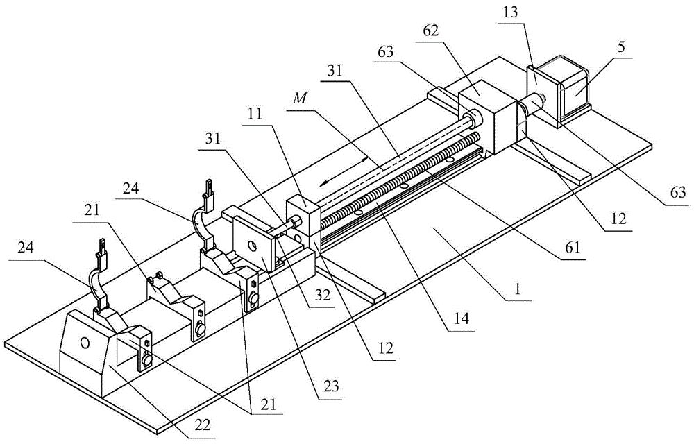
[0039] An embodiment of the device for slotting the inner wall of the spun yarn ring spinning tube designed by the present invention, such as figure 1 , figure 2 , image 3 , Figure 4 , Figure 5 , Figure 6 , Figure 7 , Figure 8 , Figure 9 , Figure 10 and Figure 11 As shown, it includes a base 1, bobbin positioning assembly, cutter bar 31, motor 5, transmission mechanism and at least one cutter 32; the base 1 is provided with a chute 11; the cutter 32 is fixed on the cutter bar 31 , the knife 32 protrudes outward from the knife bar 31; the knife bar 31 is slidably embedded in the chute 11, the center line of the knife bar 31 is set as a straight line M, and the straight line M is consistent with the sliding direction of the knife bar; the bobbin The positioning ...


PUM


Abstract

The invention discloses a slotting device for the inner wall of a spun yarn ring spinning bobbin, and belongs to the technical field of ring spun yarn equipment. The slotting device comprises a substrate, a bobbin positioning assembly, a cutter bar, a motor, a transmission mechanism and at least one cutter, wherein the substrate is provided with a sliding groove; the cutters are fixed to the cutter bar and protrude out of the cutter bar; the cutter bar is embedded in the sliding groove in a sliding manner; and the bobbin positioning assembly comprises a slotware, and the slotware is installed on the substrate and used for storing a bobbin to be processed. The motor is connected with the cutter bar through the transmission mechanism, and drives the cutter bar and the cutters to move in the longitudinal direction to cut an inner barrel of the bobbin. The slotting device is used for conducting slotting in the inner wall of the bobbin for ring spun yarns, in this way, the bobbin can be firmly attached to a spindle blade and can also be pulled out easily, and the situation that when a bobbin is pulled out, because an inner barrel of the bobbin and a spindle blade are attached too tightly, a sealing area lower than the atmosphere pressure is partially generated, and the atmosphere pressure hinders the bobbin from being pulled out is avoided.

Description

technical field [0001] The invention belongs to the technical field of ring spinning equipment, and in particular relates to the structural design of a slotting device for the inner wall of a spun ring spinning tube. Background technique [0002] In the process of ring spinning, it is necessary to remove the spun bobbin (called full bobbin or bobbin) from the spindle of the spinning machine, which is called doffing. [0003] At present, the doffing methods of ring spinning frame are divided into two categories, one is manual doffing - the bobbin is pulled out from the spindle bar by hand and put into the yarn basket, and the empty space without yarn The yarn bobbins are placed on the spindle bar; the other type is machine doffing, where the bobbins are removed one by one or in small batches with a doffer, and the empty bobbin is placed on the spindle bar with a tube insertion device, and some spun yarns The machine has its own collective doffing device, which can be used to...

Claims


Application Information

Patent Timeline
IPC IPC(8): B26D3/06B26D7/01
CPCB26D3/06B26D7/01B26D2007/013
Inventor 吴秉璋张文增曹立国
Owner TSINGHUA UNIV
Learn More