
Method for synchronously machining flange plates at two ends of rear axle housing welding assembly

A technology of synchronous processing and rear axle housing, which is applied in the direction of metal processing equipment, metal processing machinery parts, manufacturing tools, etc., can solve the problem of inability to realize multi-variety, small and medium-sized batch production, work in turn, and cannot guarantee the coaxiality of the inner hole of the flange In order to achieve the effect of reducing processing costs, reducing floor space, and improving flexibility and adaptability

Active Publication Date: 2015-11-11
INST OF LASER & OPTOELECTRONICS INTELLIGENT MFG WENZHOU UNIV
View PDF5 Cites 7 Cited by
  • Summary
  • Abstract
  • Description
  • Claims
  • Application Information

AI Technical Summary

Problems solved by technology

The processing line is long, the efficiency is low, and the cumulative value of the clamping error becomes larger due to multiple clamping at the same time
The coaxiality of the inner hole of the flange relative to the outer circle, the verticality of the end face relative to the outer circle, and the coaxiality requirements between the flanges at both ends of the axle cannot be guaranteed
[0003] In addition, the existing processing technology is not flexible and adaptable. During product transformation, fixtures, multi-axis boxes and other equipment need to be replaced, and it is impossible to realize multi-variety, small and medium-sized batch production, and work in rotation

Method used


Image

  • Method for synchronously machining flange plates at two ends of rear axle housing welding assembly
  • Method for synchronously machining flange plates at two ends of rear axle housing welding assembly
  • Method for synchronously machining flange plates at two ends of rear axle housing welding assembly

Examples


Embodiment Construction

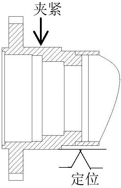
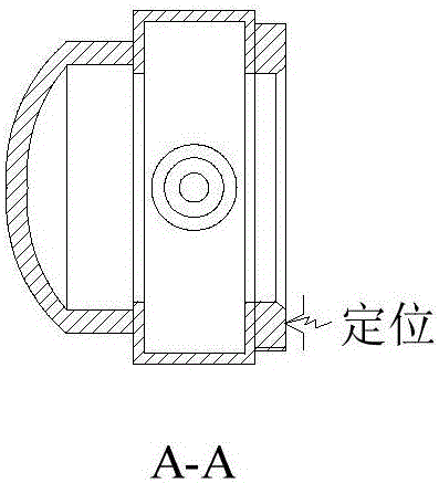
[0025] The invention provides a method for synchronously processing the flanges at both ends of the rear axle housing welding assembly, synchronously processing the outer circle, inner hole and end face of the flanges at both ends of the axle, and realizing multi-process processing in one clamping, avoiding the use of The clamping error caused by the processing of multiple machine tools can improve the machining accuracy, ensure the coaxiality of the outer circle and the inner hole, the coaxiality of the outer circle and the end face, and the coaxiality between the flanges at both ends, and reduce the machine tool. The floor area and processing time are reduced, the processing cost is reduced, and the processing quality and processing efficiency are improved.

[0026] Such as figure 2 As shown, the specific process steps for synchronously processing the flanges at both ends of the rear axle housing welding assembly are:

[0027] 1) Workpiece positioning and clamping: such as...


PUM


Abstract

The invention relates to a method for synchronously machining flange plates at the two ends of a rear axle housing welding assembly. The method comprises the steps that firstly, rough locating is conducted through a middle large hole of a rear axle housing, and V-shaped main locating and clamping are conducted through outer circles of the flanges at the two ends; secondly, main shafts at the two ends drive end face facing head end face roughing tools at the same time to rough turn large end faces and spigot end faces, and an axial machining allowance is reserved; thirdly, the main shafts at the two ends drive end face facing head end face finishing tools at the same time to fine turn the large end faces and the spigot end faces, and the requirements for the size of the large end faces, the size between the spigot end faces and the large end faces, the roughness of the large end faces, the circular run-out of the large end faces and the perpendicularity between the end faces and the axis of the outer circles of inner holes are met; fourthly, the main shafts at the two ends drive inner hole outer circle combined roughing tools to turn the spigot outer circles and the inner holes of flange heads at the two ends, and machining allowance is reserved; and finally, the main shafts at the two ends drive inner hole outer circle combined finishing tools to fine turn the spigot outer circles and the inner holes, and the requirements for coaxiality between the flanges at the two ends and the coaxiality between the inner circle and the outer circle of each flange are met. By the adoption of the method, multiple procedures are completed through one-time clamping.

Description

technical field [0001] The invention relates to a method for synchronously processing flanges at both ends of a rear axle housing welding assembly. Background technique [0002] At present, in the auto parts processing and manufacturing industry, when processing the outer circle, inner hole and end face of the flanges at both ends of the rear axle, it is necessary to process the flanges at both ends separately. After the flange, change to the other end for processing. This processing method requires the use of multiple special-purpose machine tools and multiple processes to process the workpiece. The processing line is long, the efficiency is low, and the cumulative value of the clamping error becomes larger due to multiple clamping at the same time. The coaxiality of the inner hole of the flange relative to the outer circle, the verticality of the end face relative to the outer circle, and the coaxiality requirements between the flanges at both ends of the axle cannot be ...

Claims


Application Information

Patent Timeline
Patent Type & Authority Applications(China)
IPC IPC(8): B23B5/00B23Q3/00
CPCB23B5/00B23Q3/00B23Q2703/04
Inventor 冯爱新薛伟仲秋吴浩许兴旺李峰平张华夏张津超
Owner INST OF LASER & OPTOELECTRONICS INTELLIGENT MFG WENZHOU UNIV
Learn More