Mounted Ridge Horn Phased Array Antenna Unit

A phased array antenna and ridge horn technology, applied in the fields of communication and measurement and control, can solve the problems of narrow beam width, large size of closed horn mouth, unable to meet frequency doubling bandwidth, etc., and achieve the effect of widening beam width and simple overall structure.

Active Publication Date: 2017-11-14
NO 54 INST OF CHINA ELECTRONICS SCI & TECH GRP
View PDF7 Cites 0 Cited by
  • Summary
  • Abstract
  • Description
  • Claims
  • Application Information

AI Technical Summary

Problems solved by technology

[0003] 1. Umbrella printed antenna: This form of antenna can achieve a bandwidth of about 40%, which can be used as a radiation unit for phased array scanning, but it cannot meet the bandwidth of frequency multiplication
[0004] 2. Vivaldi printed broadband antenna: This type of antenna can achieve several multiplied bandwidths, and the thickness of the antenna is relatively thin. It is more suitable for phased array antenna systems used in one-dimensional beam scanning. However, due to the feeder loss of the dielectric board, the antenna will The radiation efficiency decreases, and there is a parasitic radiation effect of the feeder, the mutual coupling in the array is large, the dielectric structure needs to be fixed with auxiliary parts, and the reliability is poor in harsh working environments
[0005] 3. Closed and ridged horn, this form is a traditional broadband antenna form, its characteristic is that the working bandwidth is more than several times the frequency, the pattern directionality is good, the polarization purity is relatively high, and it is widely used in broadband calibration In the system, due to the large size of the closed horn mouth, it is not suitable for the phased array antenna system. The beam width of the radiation pattern of the antenna is narrow, and the scanning gain of the beam scanning decreases rapidly.

Method used


Image

  • Mounted Ridge Horn Phased Array Antenna Unit
  • Mounted Ridge Horn Phased Array Antenna Unit

Examples


Embodiment Construction

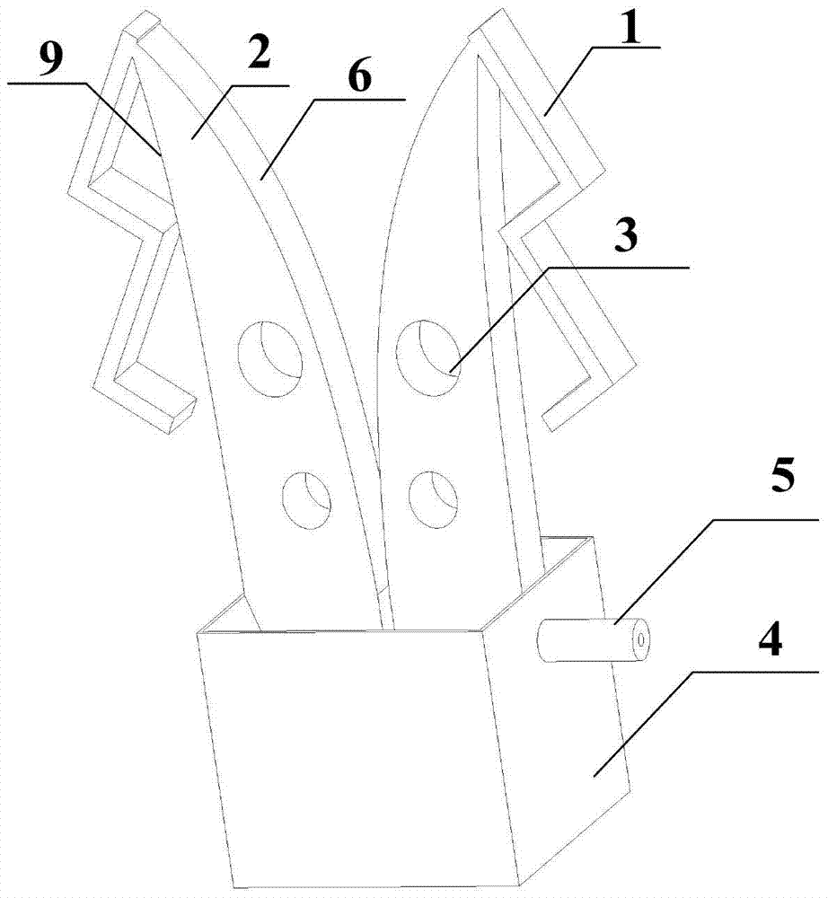
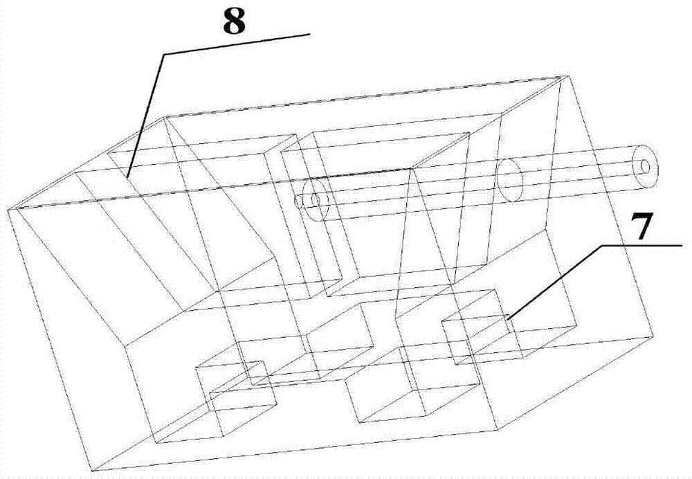
[0016] refer to figure 1 and figure 2 , a ridge horn phased array antenna unit, comprising a ridge horn antenna body, the ridge horn antenna body comprising a pair of ridge arms 2, a matching hole 3 arranged on the ridge arms, a back cavity 4 and an SMA feed connector 5. The spine arm 2 is enclosed by the inner curved surface 6 and the outer curved surface 9. It is characterized in that: a curved loading arm 1 is arranged on the outside of the outer curved surface 9, and one end of the loading arm 1 is connected to the top of the spine arm 2. Then, the other end of the loading arm 1 is a free end, and the end of the loading arm 1 connected to the top of the spine arm 2 is the top of the loading arm 1. A cross adjusting block 7 is fixedly arranged at the geometric center of the bottom plate in the back cavity 4 .

[0017] In practice, the angle of the bending part of the loading arm is 90°, or any angle between 80° and 100°.

[0018] In the present invention, the role of th...


PUM


Abstract

The invention discloses a ridge horn phased array antenna unit in the field of communication and measurement and control, which includes a ridge horn antenna body, and the ridge horn antenna body includes a pair of ridge arms, a matching hole arranged on the ridge arms, and a back cavity. and SMA feed connector, ridge arm) is surrounded by inner curved surface and outer curved surface, and a bent loading arm is arranged on the outside of the outer curved surface. One end of the loading arm is connected with the top of the ridge arm, and the loading arm The other end is a free end, and the end of the loading arm connected to the top of the spine arm is the top of the loading arm. The present invention adopts the structural form of the loaded ridge horn antenna with wide standing wave bandwidth and wide beam width designed according to the requirements of communication, measurement and control for working bandwidth, scanning angle, beam width, etc. The present invention also has small size, low loss, and reliable The invention is particularly suitable for phased array antenna systems with broadband beam scanning in communication and measurement and control systems.

Description

technical field [0001] The invention relates to a phased array antenna unit with a loaded ridge horn in the fields of communication and measurement and control. The invention is more suitable for application in communication and measurement and control phased array antenna radio frequency systems requiring broadband and wide-angle beam scanning. Background technique [0002] At present, there are mainly the following structural forms of broadband antenna units in communication and measurement and control systems. Although they have their own characteristics in terms of performance, they all have certain deficiencies. [0003] 1. Umbrella printed antenna: This type of antenna can achieve a bandwidth of about 40%, and can be used as a radiation unit for phased array scanning, but it cannot meet the bandwidth of frequency doubling. [0004] 2. Vivaldi printed broadband antenna: This type of antenna can achieve several multiplied bandwidths, and the thickness of the antenna is r...

Claims


Application Information

Patent Timeline
IPC IPC(8): H01Q13/02H01Q21/00
Inventor 宋长宏路志勇邓智勇李振生周建寨赵航
Owner NO 54 INST OF CHINA ELECTRONICS SCI & TECH GRP
Why Eureka
Try Eureka