Bracket for vertical steel reel packaging

A technology for packaging and steel coils, which is applied in the directions of packaging, transportation, packaging, and external frames. It can solve the problems that the ends are easy to touch the surface of the steel coil, the surface of the steel coil is damaged, and the size cannot be adjusted, so as to achieve simple structure and convenience. Manufacture, increase strength and durability effects

Inactive Publication Date: 2015-11-04
TONGJI UNIV
View PDF5 Cites 0 Cited by
  • Summary
  • Abstract
  • Description
  • Claims
  • Application Information

AI Technical Summary

Problems solved by technology

However, in the process of hoisting the steel coil, the end of the packaging bracket is very easy to touch the surface of the steel coil, thereby causing damage to the surface of the steel coil, so that the damaged steel coil can no longer be put into use, resulting in a waste of resources
In addition, the size of the above two packaging brackets cannot be adjusted, and cannot be applied to occasions where multiple steel coils with different outer diameters need to be packaged

Method used


Image

  • Bracket for vertical steel reel packaging
  • Bracket for vertical steel reel packaging
  • Bracket for vertical steel reel packaging

Examples


Embodiment 1

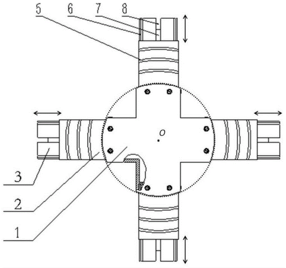
[0025] This embodiment provides a size-adjustable vertical steel coil packaging bracket, which is suitable for the occasion of packaging multiple steel coils with different outer diameters. The "upper", "lower" and "bottom" mentioned in this embodiment only mean figure 2 The relative position in , not limited to the position in real space. Such as figure 1 and figure 2 As shown, the bracket 16 for vertical steel coil packaging in this embodiment is made of steel material, and includes connectors 1 , four outer slider beams 2 and four inner slider beams 3 .

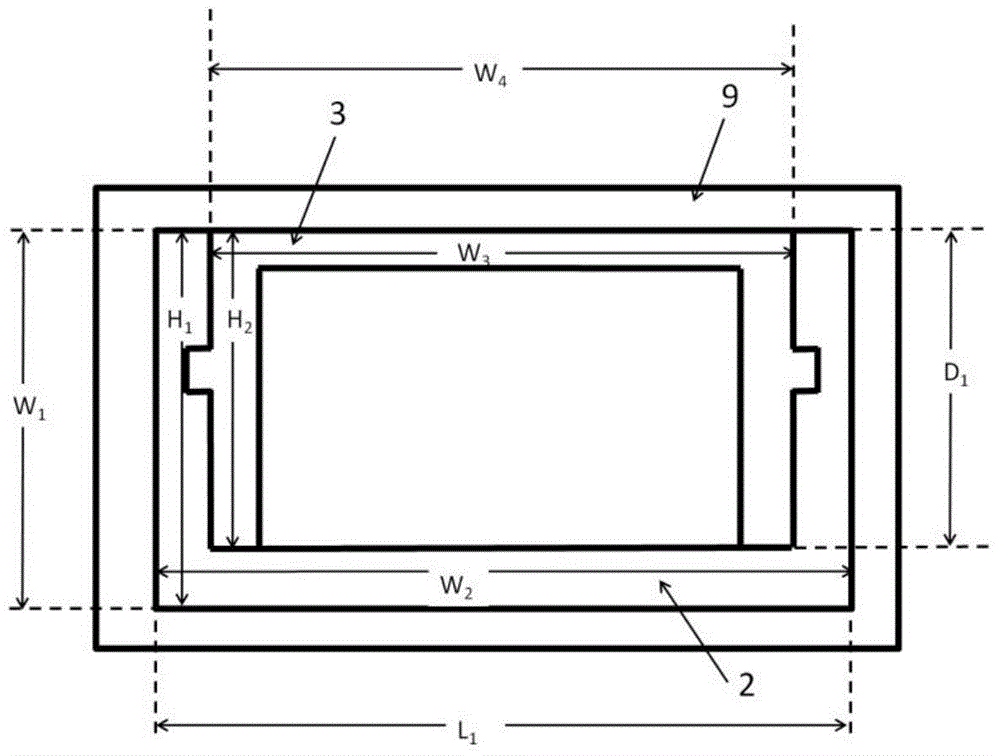
[0026] The connecting piece 1 is located in the center of the bracket 16 for vertical steel coil packaging, and has two pairs of hollow arms 9 . Each pair of arm portions 9 is symmetrical about the center of mass O of the connector 1 , so that the four arm portions 9 are arranged in a cross shape. The outer edges of the arms 9 are circular arcs, and the curvatures of the outer edges of each arm 9 are equal. Therefore...

Embodiment 2

[0033] In the first embodiment, the boss provided on the bottom of the outer slider beam extends along the width direction of the outer slider beam, however, the boss can also extend along other directions. Such as Figure 4 As shown, the bracket for vertical steel coil packaging includes connectors 10 , four outer slider beams 11 and four inner slider beams 12 . The included angle α formed by the extension direction of the plurality of bosses 13 at the bottom of the outer slider beam 11 and the tangential direction of the outer edge of the arm portion 14 of the connector 10 is 45 degrees. The distance between two adjacent bosses 13 is equal and greater than the width of the sling, which facilitates the passing of the sling during lifting, and then facilitates lifting. Similarly, it is also convenient for forklift transportation. Other structures of the bracket for vertical steel coil packaging in this embodiment are basically the same as those of the bracket for vertical ste...


PUM


Abstract

The invention provides a bracket for vertical steel reel packaging. The bracket comprises a connecting piece provided with a plurality of arms, a plurality of outer sliding block beams corresponding to the arms one to one, and a plurality of inner sliding block beams corresponding to the outer sliding block beams one to one, wherein the arms are of hollow structures; one end of each outer sliding block beam is fixedly connected with the corresponding arm; and the inner sliding block beams can be mounted in the other ends of the outer sliding block beams in a sliding way. The bracket for vertical steel reel packaging has the advantages that the structure is simple; the manufacturing is convenient; the intensity is high; the deformation is difficult; the safety is high; the service life is long, and the applicable range is wide; and the bracket is particularly suitable for conveying and hoisting of vertical steel reels by a forklift.

Description

technical field [0001] The invention belongs to the technical field of packaging equipment and relates to a packaging bracket. Background technique [0002] Vertical packaging is often used after the steel coil is produced off the assembly line. Vertical packaging means that the lower end of the steel coil is fixed on the packaging bracket, and its tube diameter is placed perpendicular to the packaging bracket. The purpose is to protect the surface of the steel coil from damage during storage and transportation of the steel coil. [0003] At present, the most commonly used packaging bracket is made of wooden materials. Although it is not easy to damage the surface of the steel coil, its strength is low, it can only be used once, and it cannot be recycled. The consumption of wood is large, which is neither economical nor environmentally friendly. ; On the other hand, the quality of wooden materials is unstable, and the packaging bracket may be damaged during the steel coil h...

Claims


Application Information

Patent Timeline
IPC IPC(8): B65D61/00B65D85/66B65D85/67
Inventor 刘海江周呈呈付志鹏
Owner TONGJI UNIV
Why Eureka
Try Eureka