
Rotating long-thin shaft sealing structure

A sealing structure and slender shaft technology, which is applied in the direction of engine sealing, engine components, mechanical equipment, etc., can solve the problems of affecting the sealing effect, wear of the slender shaft, and poor sealing effect, so as to improve the sealing effect and solve the problem of being damaged wear effect

Inactive Publication Date: 2015-10-28
HUBEI TIANSHEN INDAL
View PDF0 Cites 7 Cited by
  • Summary
  • Abstract
  • Description
  • Claims
  • Application Information

AI Technical Summary

Problems solved by technology

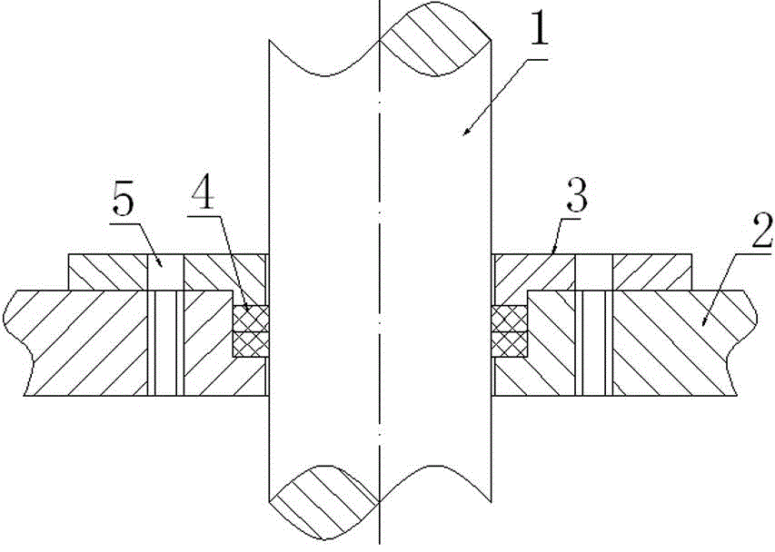
[0002] The existing screw conveyor shaft seal mostly adopts the sealing method that the gland compresses the packing packing ( figure 1 ), in the figure 1 is the rotating slender shaft, 2 is the spiral groove body, 3 is the gland, 4 is the packing material, 5 is the bolt, the rotating slender shaft 1 is in the spiral groove body 2, and the gland 3 passes through the bolt 5 Fill the packing 4 between the spiral groove body 2 and the rotating slender shaft 1. The packing 4 will rub against the rotating slender shaft 1 with a large radial runout for a long time. When the packing 4 is worn, it will also The corresponding outer part of the rotating slender shaft 1 is worn, so even if the standard new packing 4 is replaced, the sealing effect is still not good
It is very troublesome to repair the worn rotating slender shaft 1, and if the original sealing method is still used, even if the slender shaft is repaired at a high cost, the slender shaft will also be worn out in a short time, affecting the sealing effect

Method used


Image

  • Rotating long-thin shaft sealing structure
  • Rotating long-thin shaft sealing structure

Examples


Embodiment Construction

[0017] The present invention as figure 2 shown.

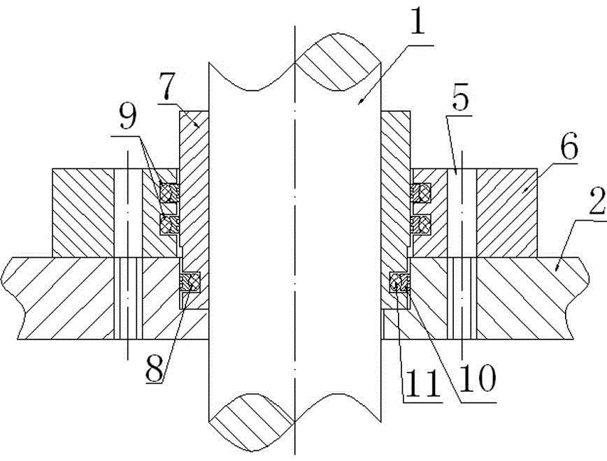
[0018] A rotating slender shaft sealing structure, comprising a rotating slender shaft 1 in a spiral groove body 2, a groove is formed on the contact surface of the spiral groove body 2 and the rotating slender shaft 1, and a shaft sleeve is arranged on the rotating slender shaft 1 7. The lower end of the shaft sleeve 7 is in the groove, and the lower end of the shaft sleeve 7 forms a seal through the rotating combined sealing structure 8 and the spiral groove body 2; the upper surface of the spiral groove body 2 is provided with an outer support body 6 through bolts 5, and the outer support body Between the body and the 6 shaft sleeves 7, there are multiple rotary combined sealing structures 29.

[0019] The axle sleeve 7 is a copper sleeve.

[0020] The part where the rotary combined sealing structure is in contact with the sealed surface is a dynamic sealing ring 10 , and a static O-ring 11 is fitted inside the dynamic se...


PUM


Abstract

The invention provides a rotating long-thin shaft sealing structure. The structure is characterized in that a rotating long-thin shaft is arranged in a spiral groove body, and a groove is formed on a contact face of the spiral groove body and the rotating long-thin shaft; a copper shaft sleeve is arranged on the rotating long-thin shaft, and the lower end of the copper shaft sleeve is arranged in the groove; a seal is formed by the lower end of the copper shaft sleeve and the spiral groove body through a first rotating combination sealing structure; an outer supporting body is arranged on the spiral groove body through bolts, and a plurality of second rotating combination sealing structures are arranged between the outer supporting body and the shaft sleeve; and dynamic sealing rings are arranged at the contact portions of the first and second rotating combination sealing structures and a sealed face, and static O-shaped rings are arranged in the dynamic sealing rings in a matched manner. Lengthened guidance is formed by the rotating long-thin shaft and the outer supporting body jointly, and the rotating function of stabilizing the rotating long-thin shaft is achieved; oversize jumping is prevented, and the effect of protecting the rotating long-thin shaft is achieved; due to using of the multiple sealing structures, the sealing effect is ensured; and the problem that the rotating long-thin shaft is worn is solved, and the sealing effect is improved.

Description

technical field [0001] The invention relates to a stirring rotary seal of dust, in particular to a rotary slender shaft sealing structure. Background technique [0002] The existing screw conveyor shaft seal mostly adopts the sealing method that the gland compresses the packing packing ( figure 1 ), in the figure 1 is the rotating slender shaft, 2 is the spiral groove body, 3 is the gland, 4 is the packing material, 5 is the bolt, the rotating slender shaft 1 is in the spiral groove body 2, and the gland 3 passes through the bolt 5 Fill the packing 4 between the spiral groove body 2 and the rotating slender shaft 1. The packing 4 will rub against the rotating slender shaft 1 with a large radial runout for a long time. When the packing 4 is worn, it will also The corresponding outer circle part of the rotating slender shaft 1 is worn, so even if the standard new packing 4 is replaced, the sealing effect is still not good. It is very troublesome to repair the worn rotating s...

Claims


Application Information

Patent Timeline
IPC IPC(8): F16J15/16F16J15/54
CPCF16J15/32F16J15/54
Inventor 王燕峰张政昝小忠周瑜王波
Owner HUBEI TIANSHEN INDAL
Learn More