
Juicer

A juicer and driving mechanism technology, applied in the field of juicers, can solve the problems of gears being easily damaged and difficult to clean, and achieve the effects of avoiding the risk of gear damage, smooth cutting of ingredients, and good flow performance.

Inactive Publication Date: 2015-10-28
孙善庆
View PDF8 Cites 5 Cited by
  • Summary
  • Abstract
  • Description
  • Claims
  • Application Information

AI Technical Summary

Problems solved by technology

However, in order to realize the relative rotation function of the net brush, the traditional design adopts the form of adding a group of gear pairs at the bottom of the casing. Specifically, a drive gear is set on the output shaft of the drive mechanism, and the drive gear drives the gear pair meshed with it. The driven gear is provided with gear teeth meshing with the driven gear on the bottom periphery of the net brush, so that the net brush can rotate in the opposite direction while the driving mechanism drives the extrusion rod part to rotate. For example, the patent The Chinese Utility Model Patent No. ZL201320624655.7 "A Juice Machine" adopts the above-mentioned structure, however, because the structure uses gears for transmission, the gears are easy to damage and difficult to clean

Method used


Image

  • Juicer
  • Juicer
  • Juicer

Examples


Embodiment Construction

[0031] The present invention will be further described in detail below in conjunction with the accompanying drawings and embodiments.

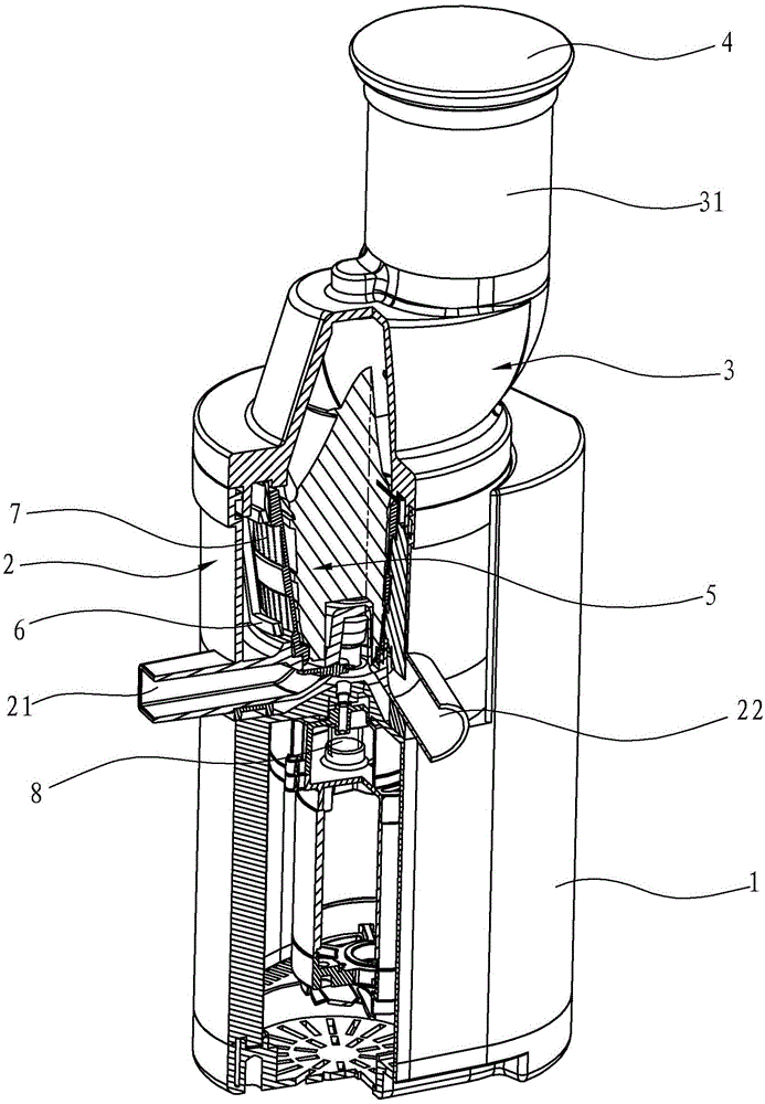
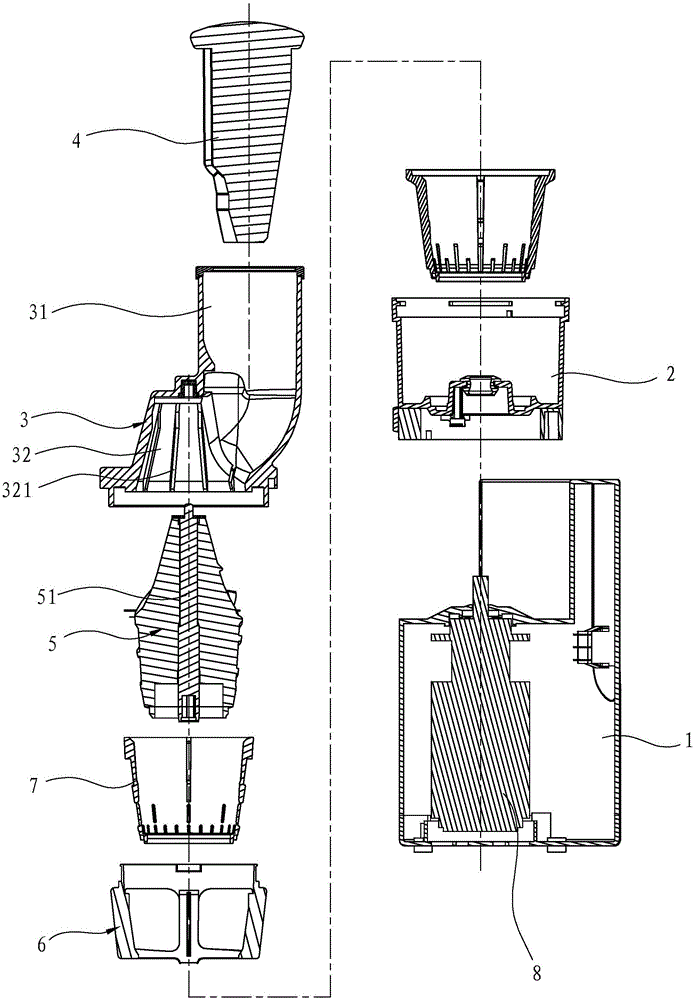
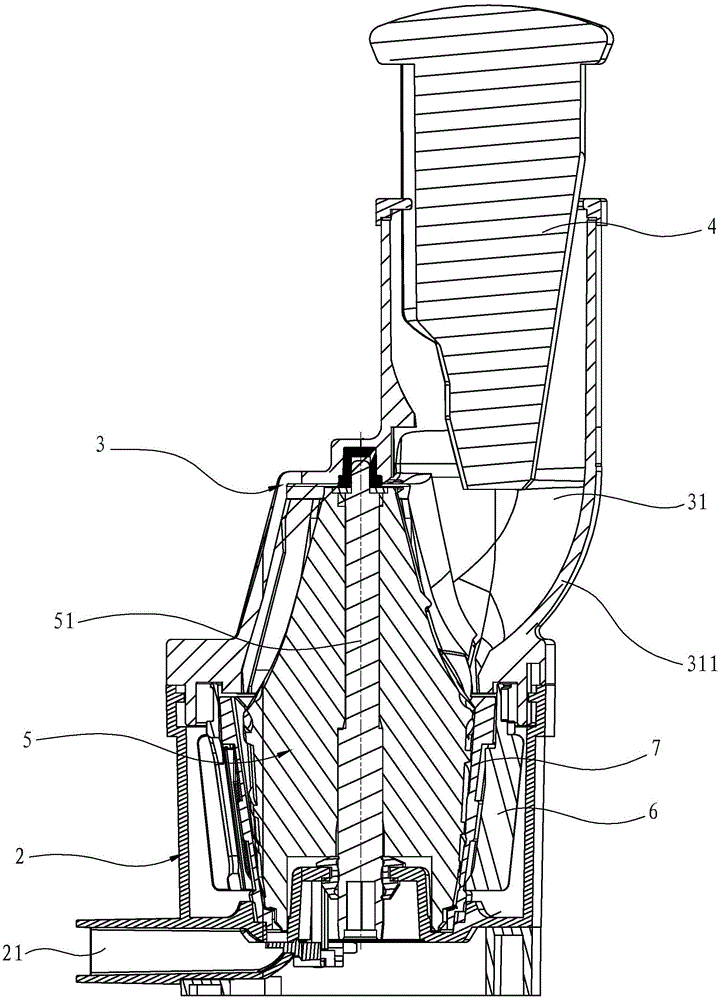
[0032] Such as Figures 1 to 16 As shown, the present invention discloses a juice machine, which includes a base 1 , a driving mechanism 8 , a cup cover 3 , a casing 2 , a filtering device 7 , an extruding rod part 5 , a net brush 6 and a pushing rod 4 .

[0033] Wherein, the driving mechanism 8 is arranged in the base 1, and the housing 2 is arranged on the base 1. The bottom of the housing 2 has a slag collection tank and a juice collection tank, and a juice outlet pipe 22 communicating with the juice collection tank extends outside the housing 2. And the slag discharge pipe 21 communicating with the slag collection tank, the cup cover 3 is arranged above the shell 2, the cup cover 3 has a cup cover inner cavity 32, and the scrap ribs 321 are arranged on the cup cover inner cavity 32 The cup cover 3 is provided with a feed channel 31 commun...


PUM


Abstract

The invention discloses a juicer which comprises a base, wherein a driving mechanism is arranged inside the base; an outer housing is arranged on the base; a juice outlet pipe and a residue discharge pipe are arranged at the bottom of the outer housing; a cup lid is arranged above the outer housing; an accommodating chamber used for processing original juice is formed inside the cup lid and the outer housing; a feeding channel for allowing food materials to enter is formed in the cup lid; a filtering device provided with meshes is arranged inside the accommodating chamber; a squeezing rod component driven by the driving mechanism to be used for squeezing food materials is arranged inside the filtering device; a cutter made of a hard material is assembled at the top of the squeezing rod component. According to the invention, the cutter and a cutting drive blade are arranged on the squeezing rod component, so that the juicer enables the food materials to flow more smoothly, enables residues to be discharged more completely, and is long in service life.

Description

technical field [0001] The invention relates to a raw juice machine. Background technique [0002] The original juice machine realizes the separation of juice residues of food materials (such as fruits, vegetables, etc.) by means of screw extrusion. Specifically, the juice machine includes a base, a driving mechanism is arranged in the base, a housing is arranged on the base, a juice outlet pipe and a slag discharge pipe are formed on the bottom of the housing, and a cup cover is arranged above the housing. The inside of the cup cover and the shell forms a cavity for raw juice processing. The cup cover is provided with a feeding channel for the food to enter, and a filter device with mesh is provided in the cavity. There is an extruding rod part driven by a drive mechanism for extruding food. When in use, put the food material from the feeding channel, and after the power is turned on, the driving mechanism drives the extruding rod part to rotate. During the screw extrusio...

Claims


Application Information

Patent Timeline
Patent Type & Authority Applications(China)
IPC IPC(8): A47J19/02A47J19/06
CPCA47J19/025
Inventor 孙善庆陈建伟
Owner 孙善庆
Learn More