
A switching control circuit for aircraft landing lights

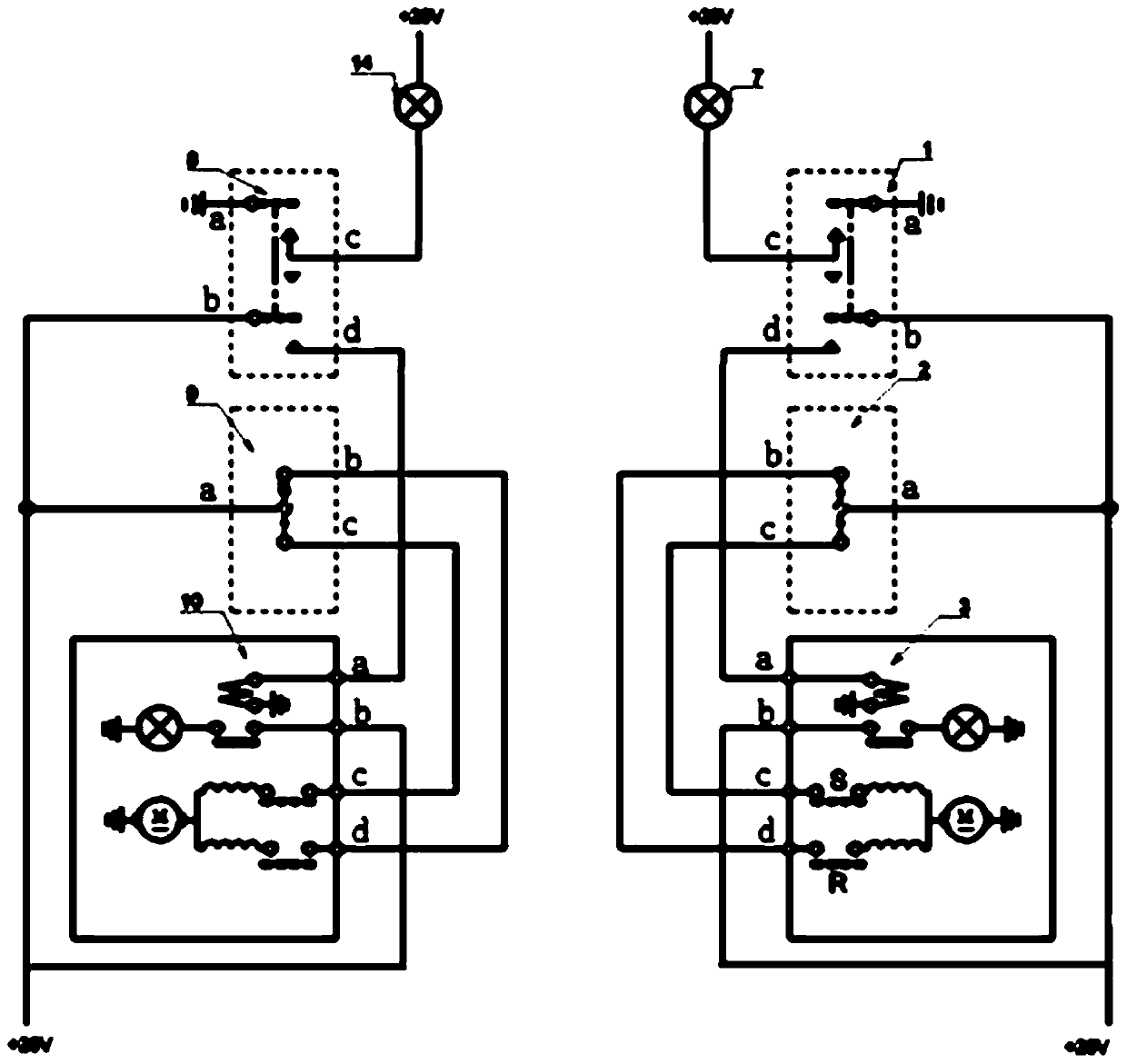
A technology for aircraft landing lights and conversion control, which is applied to the layout of electric light circuits, electric light sources, lighting devices, etc., and can solve problems such as failure to meet airworthiness requirements and failure to control landing lights

Active Publication Date: 2018-04-10
哈尔滨哈飞航空工业有限责任公司
View PDF2 Cites 0 Cited by
  • Summary
  • Abstract
  • Description
  • Claims
  • Application Information

AI Technical Summary

Problems solved by technology

[0007] Its disadvantages are: since the pilot and co-pilot control their own landing lights separately, and the right landing light control circuit and the left landing light control circuit are independent of each other, this electrical control system for landing lights is only suitable for dual-pilot flight
If a single pilot can only control the landing lights on one side of the pilot, but cannot control the landing lights on the other side, it does not meet the requirements stipulated in Article 91.407 of CCAR-91-R2 "General Operation and Flight Rules" , so it cannot meet the airworthiness requirements when flying with a single pilot

Method used


Image

  • A switching control circuit for aircraft landing lights
  • A switching control circuit for aircraft landing lights

Examples


Embodiment Construction

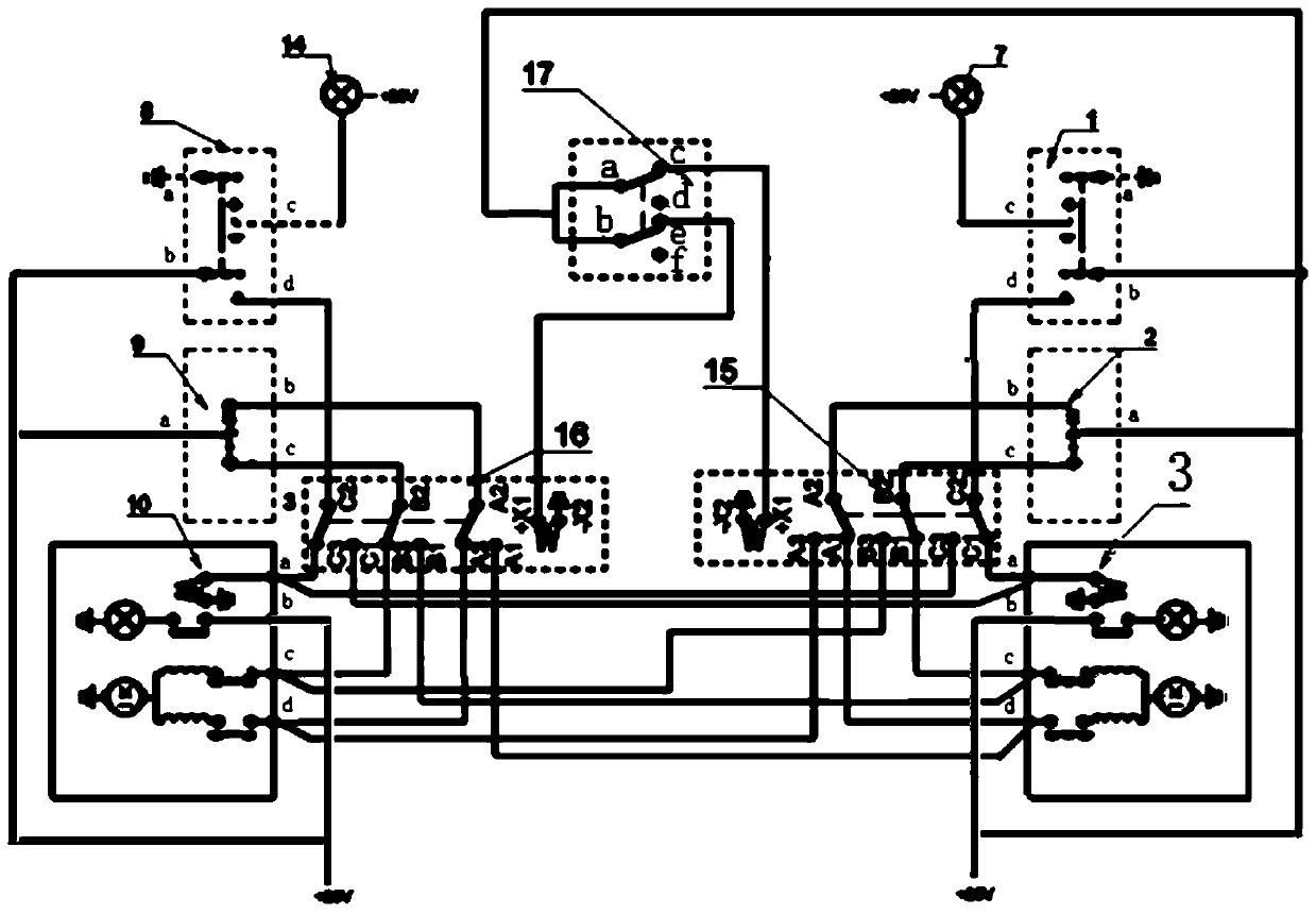
[0013] The present invention will be described in further detail below. see figure 2 , an aircraft landing light conversion control circuit, including a right landing light control circuit and a left landing light control circuit, the right landing light control circuit includes a right landing light control switch 1, a right landing light retractable switch 2, a right landing light module 3 and Right indicator light 7; right landing light control switch 1 is a linkage double pole double throw switch, one end of right indicator light 7 is connected to +28V power supply, the other end of right indicator light 7 is connected to the indicator light of right landing light control switch 1 The connection end of the indicator light is the first static contact 1c of the right landing light control switch 1, the grounding end of the right landing light control switch 1 is grounded, and the grounding end is the first moving contact 1a of the right landing light control switch 1 , the...


PUM


Abstract

The invention belongs to the aircraft electric control technology, and relates to the improvement of the control circuit of the aircraft landing light. It includes a right landing light control circuit and a left landing light control circuit, and is characterized in that it has a right transfer relay (15), a left transfer relay (16) and a transfer switch (17). The present invention proposes an improved aircraft landing light control circuit, which realizes the ability of the pilot on one side to control the landing light on the other side, and meets the requirements stipulated in Article 91.407 of CCAR-91-R2 "General Operation and Flight Rules". Require.

Description

technical field [0001] The invention belongs to the aircraft electric control technology, and relates to the improvement of the control circuit of the aircraft landing light. Background technique [0002] At present, the landing light control circuit of a certain type of aircraft can be found in figure 1 , which consists of the right landing light control circuit and the left landing light control circuit. The right landing light control circuit is composed of the right landing light control switch 1, the right landing light retractable switch 2, the right landing light module 3 and the right indicator light 7; the left landing light control circuit is composed of the left landing light control switch 8, the left landing light retractable Release switch 9, left landing light module 10 and left indicator light 14 are formed. [0003] The right landing light control switch 1 is a linkage double-pole double-throw switch. One end of the right indicator light 7 is connected to ...

Claims


Application Information

Patent Timeline
Patent Type & Authority Patents(China)
IPC IPC(8): H05B37/02
Inventor 张洪侠孙凯李昊晗马彦鹏钱恒龙杨春宝李存檀婧杰徐立罗和顺
Owner 哈尔滨哈飞航空工业有限责任公司
Learn More