


Quick Research
Generate reliable direction feasibility study reports for your R&D in just a few steps.

Technical Q&A
Discover and master advanced knowledge NOW. Basics, ideas, possibilities, all at once.

Find Solutions
As an expert in R&D theories, this can generate solutions to your technical problems instantly.

Evaluate Feasibility
Analyze your overall solution with one click, know your potential R&D risks in advance.

Monitor Landscape
Get weekly tech updates, stay abreast of the latest tech innovations and key insights.
Phase modulation laser Doppler velocity measurement system and velocity measurement method
A technology of Doppler speed measurement and phase modulation, which is applied in the phase modulation laser Doppler speed measurement system and the field of speed measurement, can solve the problems of multiple structures of components, narrow measurement range, complex sensitivity, etc., and achieve high measurement sensitivity, wide measurement range, Parts Simple Effects
- Summary
- Abstract
- Description
- Claims
- Application Information
AI Technical Summary
Problems solved by technology
Method used
Image

Examples
specific Embodiment approach 1
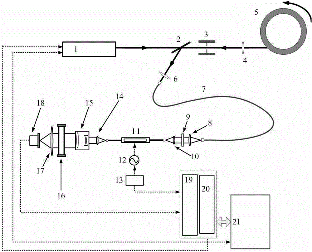
[0037] combine figure 1To illustrate this embodiment, a phase-modulated laser Doppler velocimetry system includes: a laser 1, a polarization beam splitter 2, a mechanical switch 3, a first convex lens 4, a rotating target 5, a second convex lens 6, a multimode optical fiber 7, a third Convex lens 8, polarizer 9, fourth convex lens 10, optical fiber phase modulator 11, fifth convex lens 14, beam expander 15, F-P interferometer 16, sixth convex lens 17, photomultiplier tube 18, driver 12, signal generator 13 , data acquisition card 19, output card 20 and computer 21;
[0038] When the mechanical switch 3 is turned on, the laser 1 emits signal light, passes through the polarization beam splitter 2 and then passes through the center of the first convex lens 4;
[0039] The center of the first convex lens 4 is arranged on the optical path passing through the polarizing beam splitter 2;
[0040] After the signal light passes through the center of the vibration beam splitter 2 and...
specific Embodiment approach 2
[0053] The method for realizing speed measurement by using the phase modulation laser Doppler speed measurement system comprises the following steps:
[0054] Step 1: When the mechanical switch 3 is in the closed state, use the computer 21 to control the output card 20 to adjust the output frequency of the laser 1, i.e. the frequency ω of the signal light, and use the computer 21 to collect the output frequency of the different laser frequencies collected by the data acquisition card 19. Output current i(t), draw the frequency shift change curve of nA(ω);
[0055] Step 2: When the mechanical switch 3 is closed, under the normal working condition of the phase modulation laser Doppler velocimetry system, the computer 21 collects the output current i(t) from the data acquisition card 19, and calculates nA(ω 0 ); Use the frequency shift curve of nA(ω) to determine the frequency ω of the outgoing signal light 0 value;
[0056] Step 3: When the mechanical switch 3 is turned on, th...
specific Embodiment approach 3
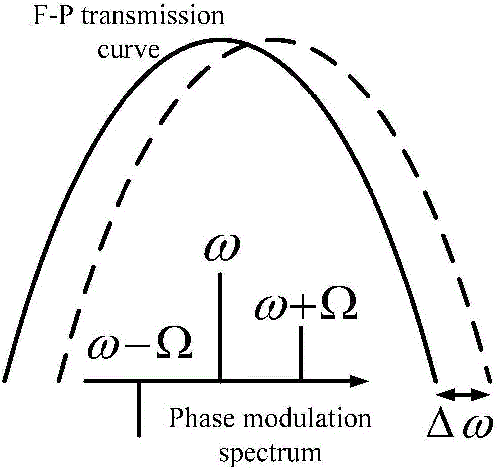
[0058] The field strength of the single-frequency signal light after sinusoidal phase modulation is expressed as
[0059] E. in =E 0 exp[j(ωt+βsinΩt)] (1)
[0060] Among them, E 0 is the incident signal light field intensity; ω is the frequency of the incident signal light; Ω is the phase modulation frequency; β is the phase modulation depth; j is a complex number; t is time;
[0061] Properly adjust the magnification of the driver 12 to make the phase modulation depth β≤0.9, and the signal light after sinusoidal phase modulation produces positive and negative first-order sidebands (second-order and above sidebands can be ignored), the field strength can be expressed as:
[0062] E. in =E 0 {J 0 (β)exp(jωt)+J 1 (β)exp[j(ω+Ω)t]-J 1 (β)exp[j(ω-Ω)t]} (2)
[0063] Among them, J 0 and J 1 are zero-order and first-order Bessel functions, respectively;
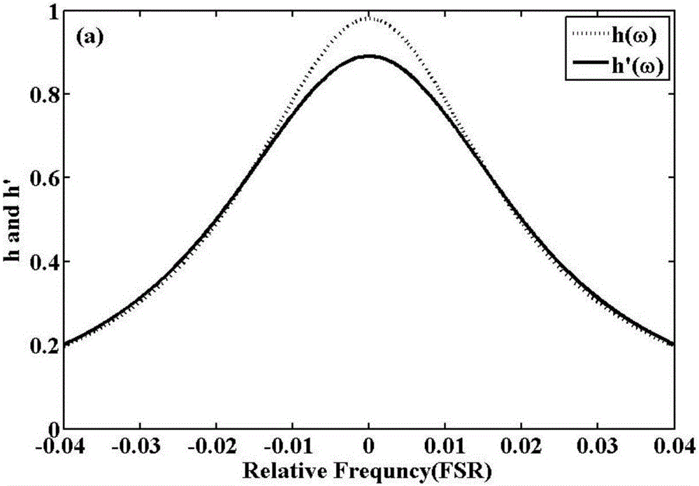
[0064] F-P interferometer transmittance curve as figure 2 As shown, after passing through the F-P interferometer 16,...
PUM
 Abstract
Description
Claims
Application Information
 - R&D Engineer
- R&D Manager
- IP Professional
- Industry Leading Data Capabilities
- Powerful AI technology
- Patent DNA Extraction
Browse by: Latest US Patents, China's latest patents, Technical Efficacy Thesaurus, Application Domain, Technology Topic, Popular Technical Reports.
© 2024 PatSnap. All rights reserved.Legal|Privacy policy|Modern Slavery Act Transparency Statement|Sitemap|About US| Contact US: help@patsnap.com