
External pressure rubber joint

A technology of rubber joints and external joints, applied in the direction of pipes/pipe joints/pipe fittings, adjustable connections, passing components, etc., can solve the problems of flattening rubber joints, construction difficulties, mechanical damage, etc. The overall performance is superior and the effect of preventing blasting danger

Active Publication Date: 2017-06-13
昌茂阀门集团有限公司
View PDF4 Cites 0 Cited by
  • Summary
  • Abstract
  • Description
  • Claims
  • Application Information

AI Technical Summary

Problems solved by technology

Among them, pipeline connection technology, as an important part of pipeline water delivery, has always been the key object of concern in this field, and the pipeline connection components involved are also being continuously optimized and improved, such as pipe joints connecting rigid pipelines. Factors such as axial displacement, angular displacement, lateral displacement, and non-parallel flanges between flanges cause difficulties in construction. Flexible rubber joints are often used to complete the connection between rigid pipelines. The rubber joints currently used in pipelines , is an internal pressure rubber joint, that is, the rubber joint is subjected to high liquid pressure inside, and the rubber product is easy to expand under the condition of internal pressure. Once the instantaneous pressure is too large, it may explode, cause danger, and cause engineering accidents; If the pump or pump is reversed, a negative pressure will be generated in the pipeline, which is very likely to suck the rubber joint and cause mechanical damage

Method used


Image

  • External pressure rubber joint

Examples


Embodiment 1

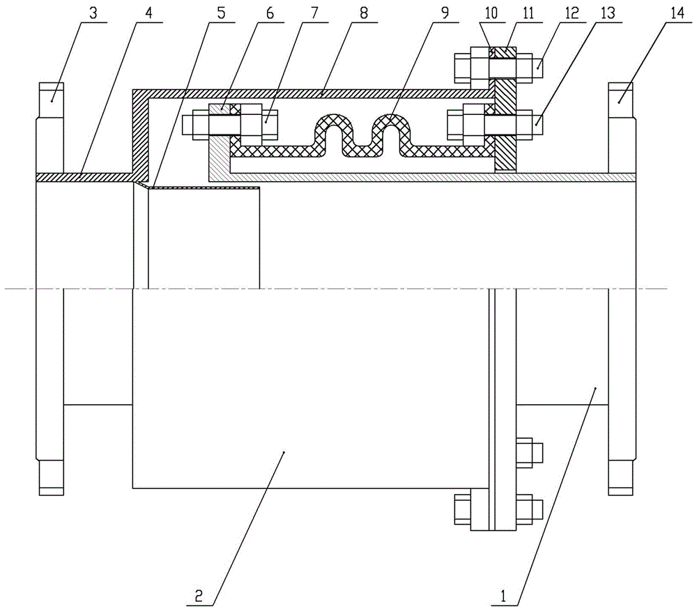
[0021] Embodiment 1: A kind of external pressure rubber joint, see figure 1 , including an outer joint 2, an inner joint 1, a connection plate 11 and a rubber compensator 9, the outer joint 2 includes an integrally formed inlet part 4 and a shell part 8, the inner diameter of the outer shell part 8 is larger than the inner diameter of the inlet part 4, and the inner diameter of the inlet part 4 A flange 3 is provided at the end of the shell part 8, and a first flange 10 is provided at the end of the outer shell part 8; the inner joint 1 includes an outlet part and a telescopic part, and the telescopic part is set in the shell part 8 of the outer joint 2, and the telescopic part A second flange 6 is provided at the end of the outlet portion, and a flange 14 is provided at the end of the outlet portion; the inner diameter of the inner joint 1 is equal to the inner diameter of the inlet portion 4 of the outer joint 2 . When using this external pressure rubber joint for pipeline c...

Embodiment 2

[0024] Embodiment 2: An external pressure rubber joint, the difference from Embodiment 1 is that the wave number of the rubber bellows used is 3.

[0025] The realization method in the above-mentioned embodiment is: the liquid flows in from the inlet part 4 of the outer joint 2, and then flows out from the outlet part of the inner joint 1. The space between the guide tube 5 and the inner wall of the inner joint 1, and the space between the second flange 6 of the inner joint 1 and the inner wall of the outer joint 2 are filled in the space between the rubber compensator 9 and the outer joint 2, such as figure 1 As shown, this part of the liquid generates pressure on the rubber compensator 9. When the internal pressure of the joint increases, the rubber compensator 9 deforms and elongates under the action of external pressure, reducing the impact and pressure, thereby effectively dispersing the internal pressure of the joint , which limits the expansion limit of the rubber joint...


PUM


Abstract

The invention discloses an external pressure rubber joint aiming to solve a technical problem of easy explosion and damage due to excessive internal pressure of a present rubber joint. The joint comprises an external joint, an internal joint, a connection disc and a rubber compensator, wherein the external joint is formed by an inlet part and a housing part; the end part of the housing part is provided with a first flange; the internal joint is formed by an outlet part and a telescopic part; the telescopic part is covered with the housing part; the end part of the telescopic part is provided with a second flange; the connection disc concentrically covers the outlet part; the first flange is fixed to the external edge of the connection disc; the rubber compensator concentrically covers the telescopic part; one end of the rubber compensator is fixed to the second flange and the other end is fixed to the internal edge of the connection disc; a connection part between the internal inlet part and the housing part of the external joint is provided with a diversion cylinder; one end of the diversion cylinder is fixed to the inner wall of the external joint; and the other end of the diversion cylinder extends to the telescopic part. The external pressure rubber joint is advantaged by pressure resistance, excellent vibration reduction and noise reduction property, safety, reliability and long service life.

Description

technical field [0001] The invention relates to the technical field of pipeline connection, mainly relates to pipeline connection parts, in particular to an external pressure rubber joint for pipeline connection. Background technique [0002] Based on the large dependence on water in today's industrial production and daily life, pipeline water transportation, as the most economical and convenient way of water transportation, has long been widely accepted and applied by the society. Among them, pipeline connection technology, as an important part of pipeline water delivery, has always been the key object of concern in this field, and the pipeline connection components involved are also being continuously optimized and improved, such as pipe joints connecting rigid pipelines. Factors such as axial displacement, angular displacement, lateral displacement, and non-parallel flanges between flanges cause difficulties in construction. Flexible rubber joints are often used to comple...

Claims


Application Information

Patent Timeline
Patent Type & Authority Patents(China)
IPC IPC(8): F16L27/12
CPCF16L27/12
Inventor 赵长茂赵朝青贺趁孙聪辉赵朝纲尹小文赵朝华庞亚磊
Owner 昌茂阀门集团有限公司
Learn More