
Multi-layer roller hearth waste heat utilization cyclic furnace and waste heat recovery method thereof

A waste heat, roller bottom technology, applied in heat treatment furnaces, furnaces, waste heat treatment and other directions, can solve the problems of high electricity price and high production cost of periodic furnaces, achieve high production efficiency, avoid hidden troubles and unsafe use, and have a wide range of applications. Effect

Active Publication Date: 2015-10-14
浙江鼎诚炉业科技有限公司
View PDF3 Cites 4 Cited by
  • Summary
  • Abstract
  • Description
  • Claims
  • Application Information

AI Technical Summary

Problems solved by technology

[0005] In addition, the existing cycle furnaces generally complete the process of heating and heat preservation during the day, and perform the process of cooling at night.
However, because the peak electricity price during the day is generally higher, the production cost of the existing cycle furnace is often high

Method used


Image

  • Multi-layer roller hearth waste heat utilization cyclic furnace and waste heat recovery method thereof
  • Multi-layer roller hearth waste heat utilization cyclic furnace and waste heat recovery method thereof
  • Multi-layer roller hearth waste heat utilization cyclic furnace and waste heat recovery method thereof

Examples


Embodiment 1

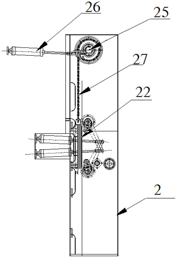
[0035] Embodiment 1: as Figures 1 to 2 As shown, the multi-layer roller bottom waste heat utilization periodic furnace described in Example 1 includes a furnace body 5, a lifter 3, a vacuum ventilation chamber 2, a feeding and discharging table 1, a transmission system, and a control system. The transmission system It includes a transmission device, the transmission device is connected with the motor, the feeding and discharging table 1, the vacuum ventilation chamber 2, the elevator 3 and the furnace body 5 are connected in sequence, and an electric motor is installed between the furnace body 5 and the elevator 3 A furnace door 4, a furnace shell 51 is provided outside the furnace body 5, a refractory insulation layer 52 is provided around the hearth of the furnace body 5, and a plurality of heating bodies 54 and at least two layers of furnace inner rollers 53 are provided in the inner furnace of the furnace body 5. , the supporting rollers 53 in each layer of the furnace ar...

Embodiment 2

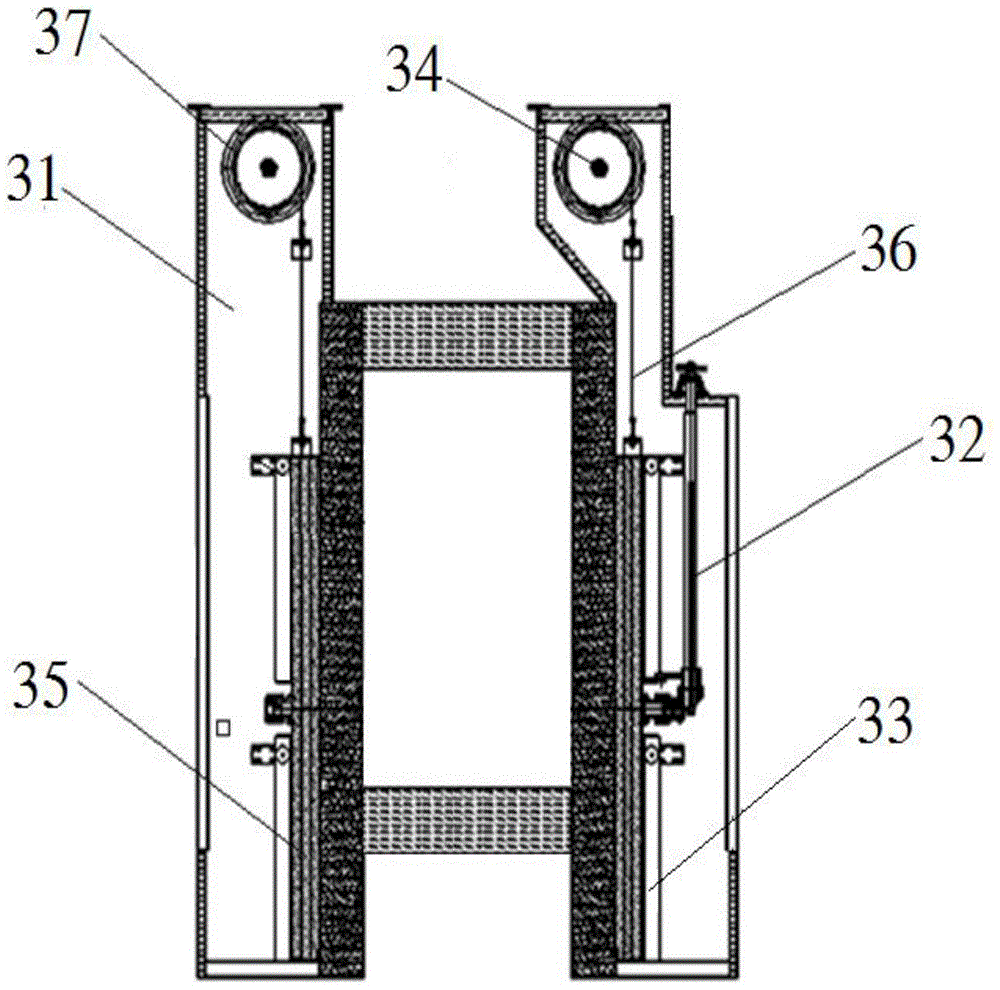
[0036] Embodiment 2: As a preferred embodiment, the difference between the multi-layer roller bottom waste heat utilization cycle furnace described in Embodiment 2 and Embodiment 1 is that the elevator 3 is provided with a shell, and the lifting area in the elevator 3 is The top and bottom are provided with thermal insulation layers.

[0037] In the multi-layer roller bottom waste heat utilization cycle furnace described in Embodiment 1 and Embodiment 2, the metal workpiece passes through the feeding and discharging idler roller 12 on the feeding and discharging table 1, the air chamber idler roller 21 in the vacuum ventilation chamber 2, The driving rollers on the lifting rack are driven by the transmission device to be transmitted to the inner rollers 53 of each layer of furnace in the furnace body 5 . Wherein, since at least two layers of furnace rollers 53 are arranged in the body of furnace 5, and a lifter 3 is provided on one side of the body of furnace 5, metal workpiec...


PUM


Abstract

The invention relates to a multi-layer roller hearth waste heat utilization cyclic furnace and a waste heat recovery method applied to the multi-layer roller hearth cyclic furnace. The multi-layer roller hearth waste heat utilization cyclic furnace comprises a furnace body, an elevator, a vacuum ventilation chamber, a material inlet and outlet table, a transmission system and a control system. The transmission system comprises a transmission device which is connected with a motor. The material inlet and outlet table, the vacuum ventilation chamber, the elevator and the furnace body are sequentially connected. An electric furnace door is arranged between the furnace body and the elevator. A furnace shell is arranged outside the furnace body. Multiple heating bodies and at least two layers of in-furnace carrier rollers are disposed in the furnace body. The in-furnace carrier rollers of each layer are arranged on the transmission device. The control system controls forward and reversing transmission of the transmission device and ascending and descending of a lifting movable table. Compared with a continuous furnace and a cyclic furnace in the prior art, the multi-layer roller hearth waste heat utilization cyclic furnace has the advantages that charge capacity is large, the application range is wide, energy consumption for production is low and production efficiency is high.

Description

technical field [0001] The invention relates to a heat treatment furnace, in particular to a multilayer roller bottom waste heat utilization cycle furnace and a waste heat recovery method applied to a multilayer roller bottom waste heat utilization cycle furnace. Background technique [0002] Heat treatment furnace is a kind of equipment used for heat treatment of metal workpieces. According to the heating method, it can be divided into flame furnace and electric furnace. According to the thermal system, it can be divided into cycle furnace and continuous furnace. Among them, the continuous furnace refers to the continuous production of the furnace, the furnace is divided into temperature zones, and the workpieces gradually enter the temperature control zone from the preheating zone. The metal workpiece processed by the continuous furnace has the characteristics of smooth surface, uniform hardness and small deformation. However, the current continuous furnaces are all singl...

Claims


Application Information

Patent Timeline
IPC IPC(8): C21D9/00F27D17/00
CPCY02P10/25
Inventor 范本龙范本良王月琴李开来
Owner 浙江鼎诚炉业科技有限公司
Learn More