
A bonding head device

A bonding head and spline shaft technology, which is applied in the field of semiconductor packaging, can solve the problem of large Z-direction size of the bonding head device, achieve the effects of reducing the Z-direction size and installation space, improving precision, and ensuring linear motion

Inactive Publication Date: 2017-08-25
CETC BEIJING ELECTRONICS EQUIP
View PDF3 Cites 0 Cited by
  • Summary
  • Abstract
  • Description
  • Claims
  • Application Information

AI Technical Summary

Problems solved by technology

[0004] The present invention provides a bonding head device, the purpose of which is to solve the problem that the rotating motor of the existing bonding head device is mostly installed above the entire device, causing the Z-direction size of the bonding head device to be too large

Method used


Image

  • A bonding head device
  • A bonding head device
  • A bonding head device

Examples


Embodiment Construction

[0027] In order to make the technical problems, technical solutions and advantages to be solved by the present invention clearer, the following will describe in detail with reference to the drawings and specific embodiments.

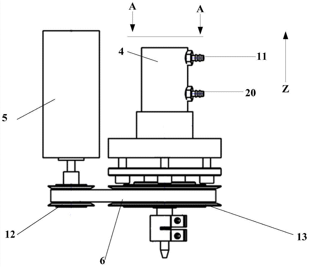
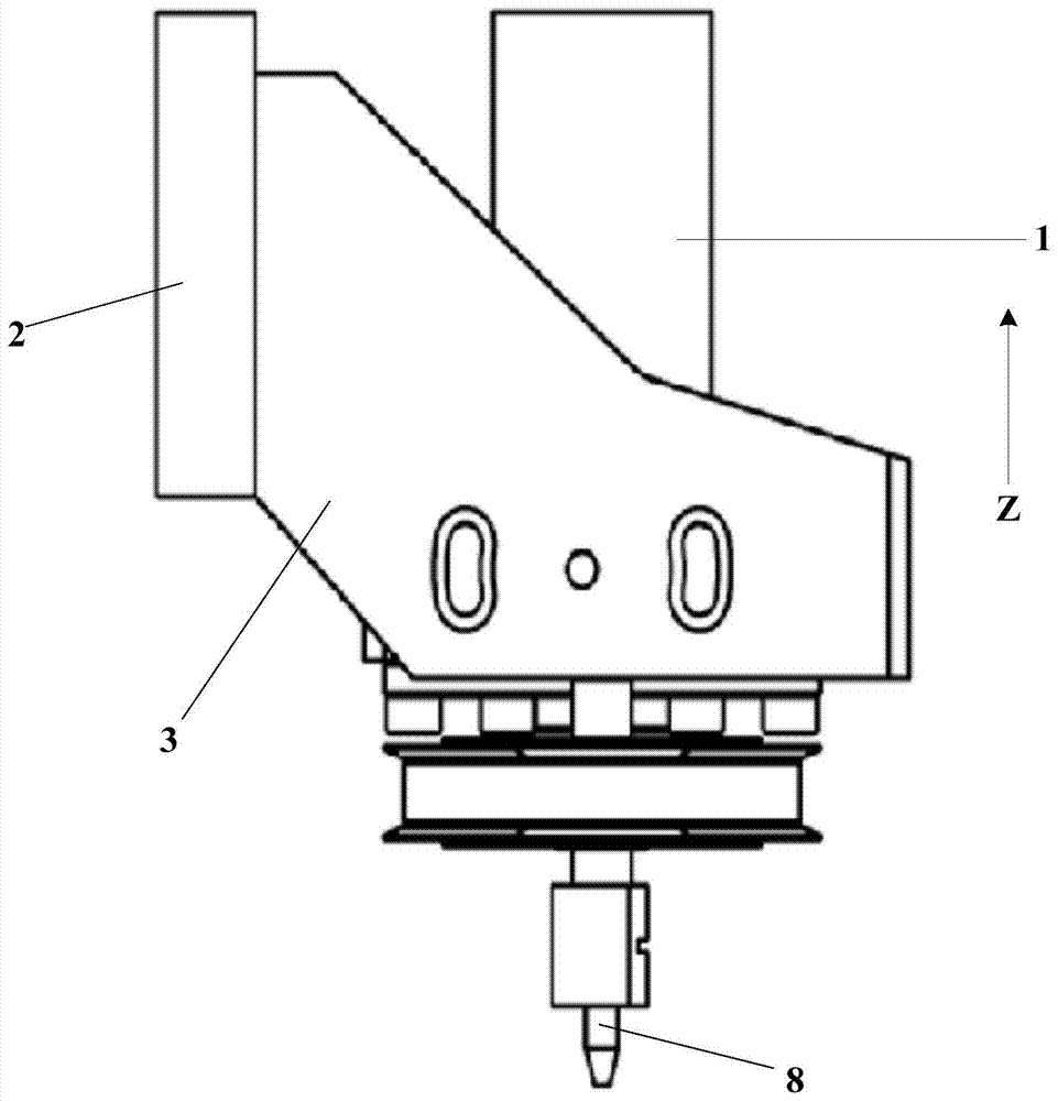
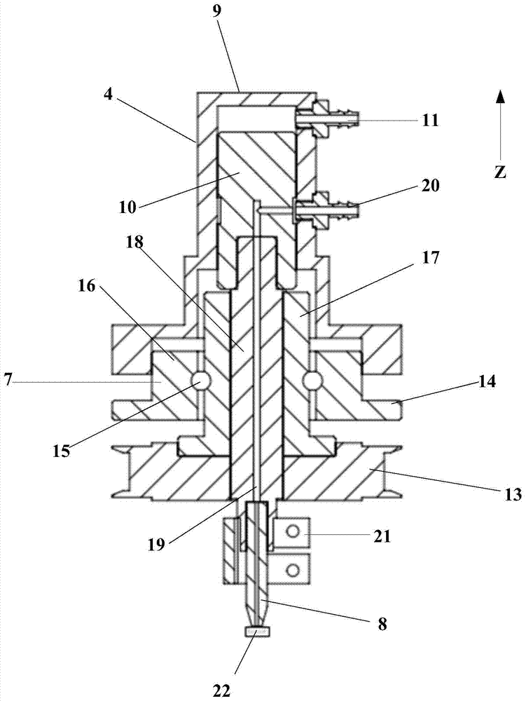
[0028] see Figure 1 to Figure 3 , the present invention provides a bonding head device for the existing problems, the device includes: a device body 1, a linear slider 2 for connecting with the external drive, a connecting device body 1, a linear slider 2 Fix the bracket 3; further, the linear slider 2 is connected with the external linear motor drive or the lead screw drive, and then drives the bonding head device to perform linear motion; preferably, three sets of linear drives can be used to set X, Y, and Z respectively. The three-direction linear guide rail realizes the movement of the bonding head device in three directions, and position sensors and grating scales can be installed on the linear guide rail to improve the position accuracy of the bon...


PUM


Abstract

The invention provides a bond head device. The device comprises a device body, a linear slide block which is in drive connection with the outside, and a fixation bracket which is connected with the device body and the linear slide block. The device body comprises a cylinder structure, a servo motor under external drive control, a transmission structure, a spline shaft structure and a vacuum suction lever which is used for adsorbing chips. The spline shaft structure comprises a sleeve, a ball and a spline shaft which matches the sleeve. The output end of the servo motor is connected with a drive wheel of the transmission structure. A driven wheel of the transmission structure is connected with the spline shaft. The cylinder structure is fixed above the spline shaft structure and matches the spline shaft structure to form a closed structure. According to the invention, the Z direction size and the installation space of the bond head device are effectively reduced, which is important for optimizing the size of each component; the spline shaft structure is used as a guide system, which can ensure high-precision linear motion of the vacuum suction lever; and the chip operation precision can be effectively improved.

Description

technical field [0001] The invention relates to the technical field of semiconductor packaging, in particular to a bonding head device. Background technique [0002] With the rapid development of global electronic information technology, integrated circuit chips continue to develop in the direction of high density, high performance, and light, thin, short, and small. The traditional wire bonding technology can no longer meet the current needs, and the flip chip The development of chip technology has brought hope for high-density packaging. Flip chip technology is a packaging process method in which semiconductor chips are directly bonded and interconnected with a substrate with a bump array structure. Compared with traditional wire bonding technology, it has many obvious advantages, including: superior electrical and thermal properties, High I / O pin count, small package size, etc., so it is gradually becoming a package form frequently used in high-end devices and high-densi...

Claims


Application Information

Patent Timeline
Patent Type & Authority Patents(China)
IPC IPC(8): H01L21/67
CPCH01L21/67126
Inventor 叶乐志王家鹏王磊
Owner CETC BEIJING ELECTRONICS EQUIP
Learn More