


Quick Research
Generate reliable direction feasibility study reports for your R&D in just a few steps.

Technical Q&A
Discover and master advanced knowledge NOW. Basics, ideas, possibilities, all at once.

Find Solutions
As an expert in R&D theories, this can generate solutions to your technical problems instantly.

Evaluate Feasibility
Analyze your overall solution with one click, know your potential R&D risks in advance.

Monitor Landscape
Get weekly tech updates, stay abreast of the latest tech innovations and key insights.
Rotary testing platform for damping loop structure for guided flying object
A loop structure and verification platform technology, which is applied in the testing of machines/structural components, measuring devices, instruments, etc., can solve problems such as damping loop structure verification or lack of testing technology, shorten test time and complexity, and ensure safe operation , High stability effect
- Summary
- Abstract
- Description
- Claims
- Application Information
AI Technical Summary
Problems solved by technology
Method used
Image

Examples
Embodiment 1
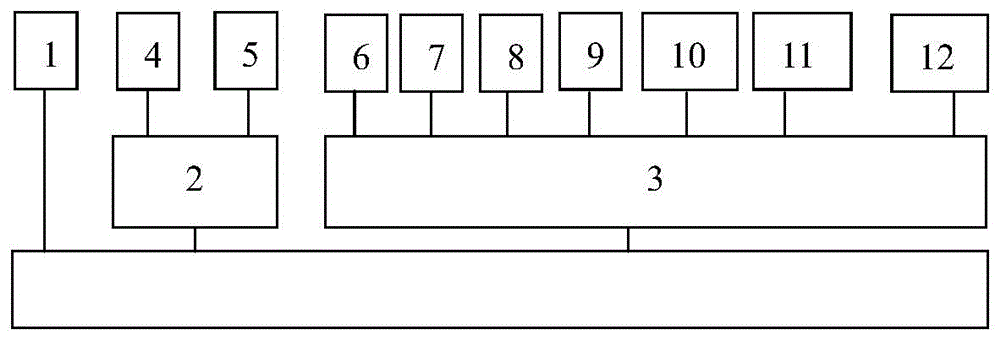
[0032] Embodiment 1: as attached figure 1 As shown in or 2, the power supply 6, product testing device 7, turntable control module 8, support control module 9, combined force decomposition module 10, data acquisition and analysis module 11 and industrial computer 12 in the product comprehensive test system 3 are collectively installed in the same control cabinet inside the device.
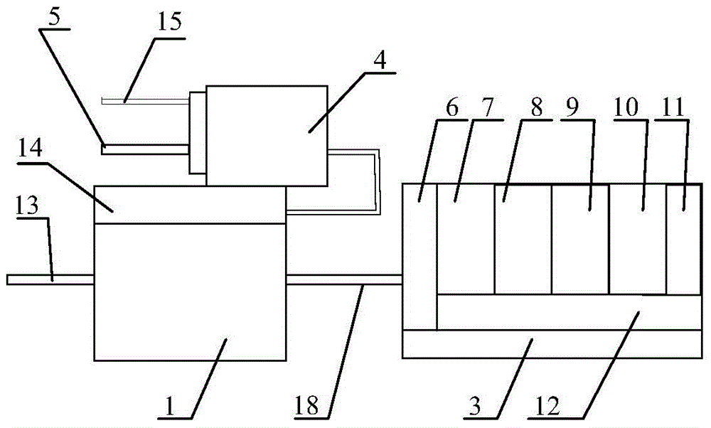
[0033] In the foregoing, the turntable mechanism 1 and the rotating bracket 4 are clamping and supporting devices for the tested product, and the tested product 19 is clamped on the rotating bracket 4 to realize motion and posture simulation.
[0034] In the foregoing, the main shaft of the turntable mechanism 1 and the main shaft of the rotating support 4 are both hollow structures, leaving a reasonable space for the arrangement of the gas supply pipeline.
[0035] In the above, in order to ensure the safety and reliability of the damping circuit design verification platform, the rotating bracket...
Embodiment 2
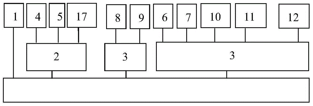
[0036] Embodiment 2: as attached image 3 , 4 Or as shown in 5, a rudder moment loading device 5 and a reference rudder deviation signal acquisition device 17 are installed at the front of the rotating bracket 4; the control part equipment of the product comprehensive testing system 3 is respectively installed on two mutually independent control cabinets, wherein the turntable control module 8 and the bracket control module 9 are installed on the industrial computer of the first control cabinet; the power supply 6, the product testing device 7, the combined force decomposition module 10, the data acquisition and analysis module 11, and the industrial computer 12 are installed on the second control cabinet.
[0037] In the foregoing, a power supply 6, an industrial computer 12 and a driver 25 are installed on the first control cabinet where the turntable control module 8 and the support control module 9 are installed, wherein a program-controlled processor 26 is installed on th...
PUM
 Abstract
Description
Claims
Application Information
 - R&D Engineer
- R&D Manager
- IP Professional
- Industry Leading Data Capabilities
- Powerful AI technology
- Patent DNA Extraction
Browse by: Latest US Patents, China's latest patents, Technical Efficacy Thesaurus, Application Domain, Technology Topic, Popular Technical Reports.
© 2024 PatSnap. All rights reserved.Legal|Privacy policy|Modern Slavery Act Transparency Statement|Sitemap|About US| Contact US: help@patsnap.com