
Diversion tunnel plug head exhaust structure and exhaust method thereof

An exhaust method and technology of diversion tunnels, applied in water conservancy projects, hydroelectric power stations, hydroelectric power generation, etc., can solve the problems of difficult control of the exhaust process, poor construction operability, unfavorable structural safety, etc., and achieve good social and economic benefits Benefits, short exhaust time, low engineering investment

Active Publication Date: 2015-10-07
CHINA POWER CONSRTUCTION GRP GUIYANG SURVEY & DESIGN INST CO LTD
View PDF7 Cites 5 Cited by
  • Summary
  • Abstract
  • Description
  • Claims
  • Application Information

AI Technical Summary

Problems solved by technology

However, in this exhaust structure, the exhaust steel pipe and the drain steel pipe are pre-buried on the top of the plug for water filling and exhaust. Valves are installed at the ends of the exhaust steel pipe and the drain steel pipe. After flushing and exhausting, the water pressure can only be resisted through a valve at the end. , in the case of high water head and valve aging, leakage channels will be formed from the exhaust pipe and drain pipe, which is extremely unfavorable to the structural safety
In this technical solution, the exhaust pipe is arranged on the top of the plug, there is no elbow in the front section of the exhaust pipe, and the exhaust direction is consistent with the drainage direction, so the pipe will be blocked, the exhaust process is difficult to control, and the specific construction operability is poor; Also difficult to contact grout for drain and exhaust steel pipes

Method used


Image

  • Diversion tunnel plug head exhaust structure and exhaust method thereof
  • Diversion tunnel plug head exhaust structure and exhaust method thereof
  • Diversion tunnel plug head exhaust structure and exhaust method thereof

Examples


Embodiment Construction

[0034] The technical solution of the present invention is further described below, but the scope of protection is not limited to the description.

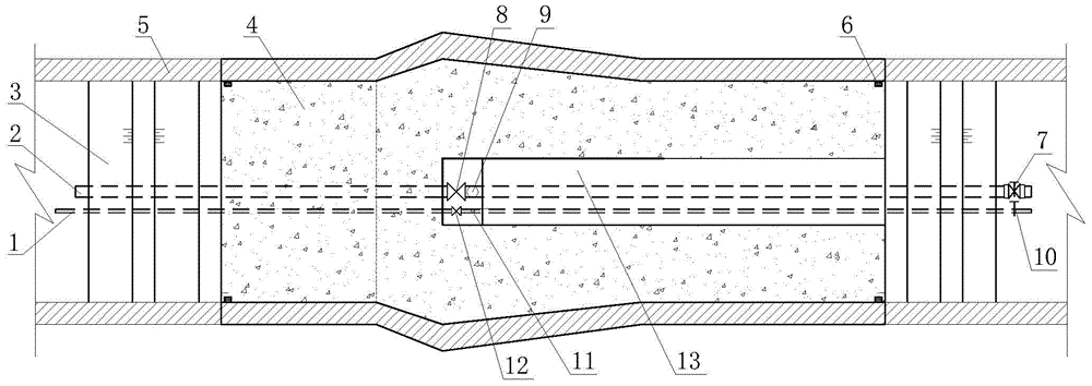
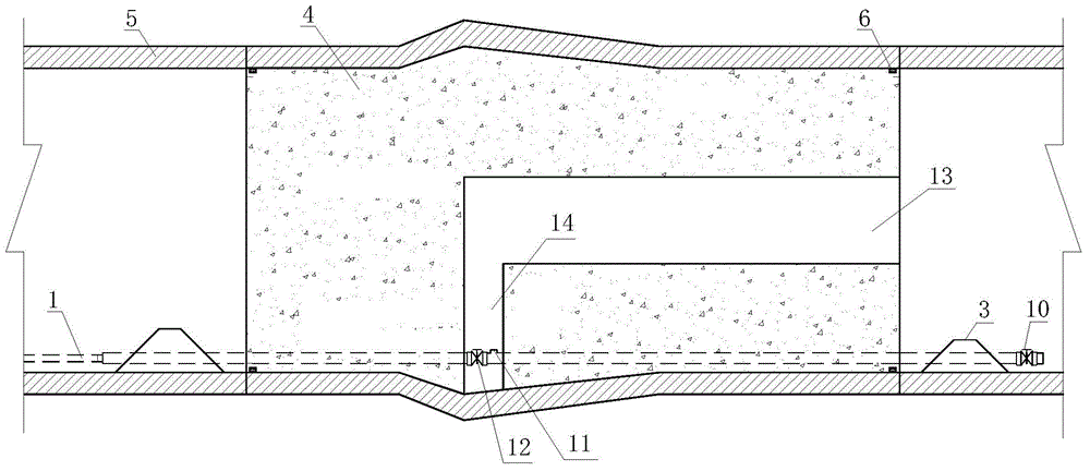
[0035] Such as figure 1 , figure 2 , image 3 As shown, the exhaust structure of a diversion tunnel plugging head according to the present invention includes a diversion cylinder 5 and a concrete plug 4 arranged in the inner sealing area of ​​the diversion cylinder 5, and the bottom of the concrete plug 4 is pre- An exhaust pipe 1 and a drain pipe 2 are buried, and cofferdams 3 are arranged on the upstream and downstream sides of the concrete plug 4 in the guide tube 5, and a grouting gallery 13 and a grouting gallery are also arranged in the concrete plug 4. The gate well 14 that road 13 communicates with. With this technical solution, during construction, the cofferdam 3 is built before the concrete plug 4, and the pre-buried drainage pipe 2 is used to drain water, so as to provide dry ground conditions for the construction o...


PUM


Abstract

The invention discloses a diversion tunnel plug head exhaust structure and an exhaust method thereof; the diversion tunnel plug head exhaust structure comprises a diversion cylinder and a concrete plug head arranged in a blocking segment in the diversion cylinder; the bottom of the concrete plug head is pre-buried with an air discharge pipe and a water discharge pipe; an upstream and a downstream of the concrete plug head in the diversion cylinder are respectively provided with a cofferdam; a grouting gallery and a gate well connected with the grouting gallery are arranged in the concrete plug head; the exhaust method comprises the following steps: 1, paving the air discharge pipe and the water discharge pipe; 2, building the cofferdams; 3, opening a water discharge butterfly valve; 4, casting the concrete plug head; 5, opening an air discharge butterfly valve; 6, observing air discharge pipe water discharge conditions. In certain regions, the diversion tunnel is deeply buried, the top is steep and no drilling construction road can be paved, and vent holes are hard to tap; the diversion tunnel plug head exhaust structure and the exhaust method can be applied to the diversion tunnel plugging construction process, thus fast discharging a cavity in the front segment of the diversion tunnel, preventing gas explosion caused by boosting pressure, and ensuring safety of the plug head structure.

Description

technical field [0001] The invention relates to an exhaust structure of a diversion tunnel plugging head and an exhaust method thereof, belonging to the technical field of water conservancy and hydropower engineering. Background technique [0002] After the construction of the diversion tunnel plug is completed, a cavity will be formed between the diversion tunnel plug and the inlet gate. As the reservoir stores water and the water level rises, the cavity will be continuously compressed by seepage water. When the pressure value reaches When the value is certain, there may be a gas explosion. In the existing technology, the front part of the diversion hole plug is drilled to form a vent hole connecting the external atmosphere and the cavity. With the water seepage in the front part of the diversion hole, the exhaust is continuously exhausted, and the exhaust is slow, and the cavity exists. It takes a long time and the construction is difficult. For diversion tunnels with dee...

Claims


Application Information

Patent Timeline
Patent Type & Authority Applications(China)
IPC IPC(8): E02B9/06
CPCY02E10/20
Inventor 王向予郑庆安
Owner CHINA POWER CONSRTUCTION GRP GUIYANG SURVEY & DESIGN INST CO LTD
Learn More