


Quick Research
Generate reliable direction feasibility study reports for your R&D in just a few steps.

Technical Q&A
Discover and master advanced knowledge NOW. Basics, ideas, possibilities, all at once.

Find Solutions
As an expert in R&D theories, this can generate solutions to your technical problems instantly.

Evaluate Feasibility
Analyze your overall solution with one click, know your potential R&D risks in advance.

Monitor Landscape
Get weekly tech updates, stay abreast of the latest tech innovations and key insights.
Dust catcher for blast furnace gas
A technology of blast furnace gas and dust collector, which is applied in the direction of blast furnace, dust collector, blast furnace details, etc., can solve the problems of faster blast furnace gas flow rate, hinder the separation of coarse dust, limit the height of cyclone dust collector, etc., and achieve the effect of simple structure
- Summary
- Abstract
- Description
- Claims
- Application Information
AI Technical Summary
Problems solved by technology
Method used
Image

Examples
no. 1 Embodiment approach
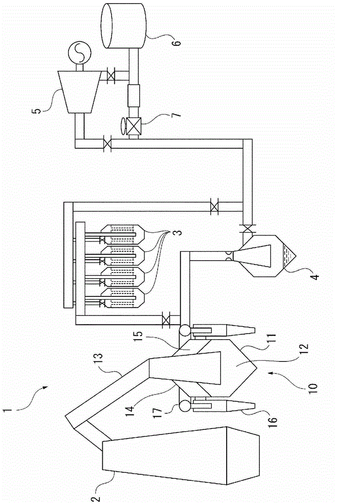
[0044]figure 1 It is a schematic diagram showing the overall configuration of the blast furnace gas purification system 1 according to the first embodiment of the present invention.
[0045] The blast furnace gas cleaning system 1 is a device for collecting dust (powder) from the blast furnace gas discharged from the top of the blast furnace 2, and has a dust collector 10 according to the present invention, and has a dry type dust collector such as an electric dust collector. Dust collector 3, Venturi dust collector and other wet dust collectors 4, furnace top pressure recovery turbine (TRT) 5, gas cabinet 6, pressure reducing valve 7.
[0046] In the blast furnace gas purification system 1, the blast furnace gas discharged from the top of the blast furnace 2 is collected by the dust collector 10 to form a semi-clean gas and sent to the secondary dust collector. The secondary dust collector usually uses a dry dust collector 3 to collect particulate dust. When the temperature ...
no. 2 Embodiment approach
[0075] Figure 5 The second embodiment of the present invention is shown.
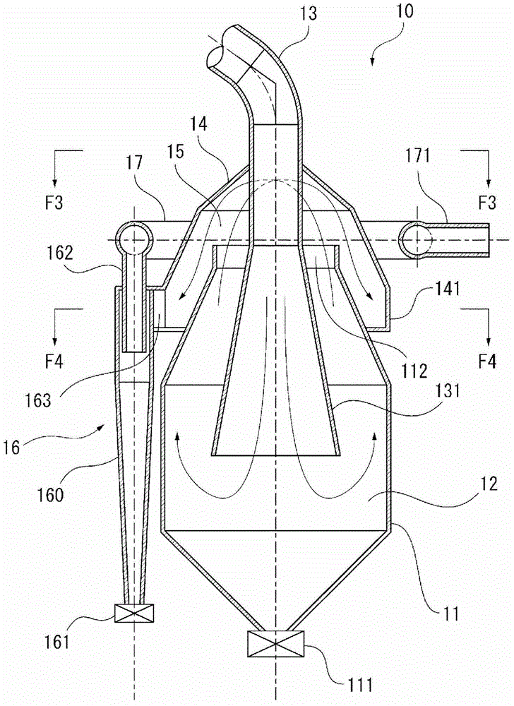
[0076] In this embodiment, except that the diffusers 21 and 22 are provided inside the upper opening 112 and the cover member 14, other structures are the same as those described above. Figure 1 ~ Figure 4 The first embodiment shown is the same. Therefore, repeated descriptions are omitted, and only different structures will be described below.
[0077] A disc-shaped diffuser 21 is provided inside the upper opening 112 .
[0078] The diffuser 21 is formed of an annular steel plate, which protrudes from the inner circumference of the opening edge of the upper opening 112 to the inner side of the opening to form an inner flange. On the lower surface side of the diffuser 21, steel plates are welded at predetermined intervals. Reinforcing plate 211 .
[0079] A cylindrical diffuser 22 is provided inside the cover member 14 .
[0080] The diffuser 22 is formed of a cylindrical steel material, protrude...
no. 3 Embodiment approach
[0090] Figure 7 The third embodiment of the present invention is shown.
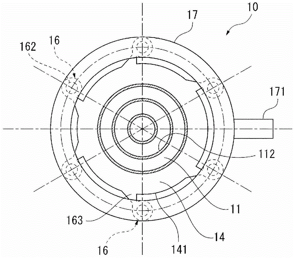
[0091] This embodiment has the same Figure 1 ~ Figure 4 The shown first embodiment has the same configuration, but the shape of the suction port 163 of the cyclone 16 is different from that of the first embodiment.
[0092] That is, in the first embodiment, as Figure 4 As shown, the suction port 163 of the cyclone dust collector 16 is in the shape of expanding on the side close to the distribution chamber 15 . In this regard, the suction port 163 of the present embodiment is a slit-shaped passage with a certain width whose shape on the side close to the distribution chamber 15 is the same as that on the side close to the main body 160 .
[0093] According to this embodiment as described above, the respective effects of the first embodiment described above can be respectively obtained.
[0094] However, the effect of suppressing the flow velocity on the side closer to the distribution chamber 15 by...
PUM
 Abstract
Description
Claims
Application Information
 - R&D Engineer
- R&D Manager
- IP Professional
- Industry Leading Data Capabilities
- Powerful AI technology
- Patent DNA Extraction
Browse by: Latest US Patents, China's latest patents, Technical Efficacy Thesaurus, Application Domain, Technology Topic, Popular Technical Reports.
© 2024 PatSnap. All rights reserved.Legal|Privacy policy|Modern Slavery Act Transparency Statement|Sitemap|About US| Contact US: help@patsnap.com