Refrigerating cycle device
A refrigeration cycle and condenser technology, applied in the field of refrigeration cycle devices, can solve the problems of low refrigeration cycle efficiency, complex refrigeration cycle management and control, etc., and achieve the effect of shortening the start-up time and stabilizing the amount of refrigerant in operation
- Summary
- Abstract
- Description
- Claims
- Application Information
AI Technical Summary
Problems solved by technology
Method used
Image
Examples
Embodiment 1
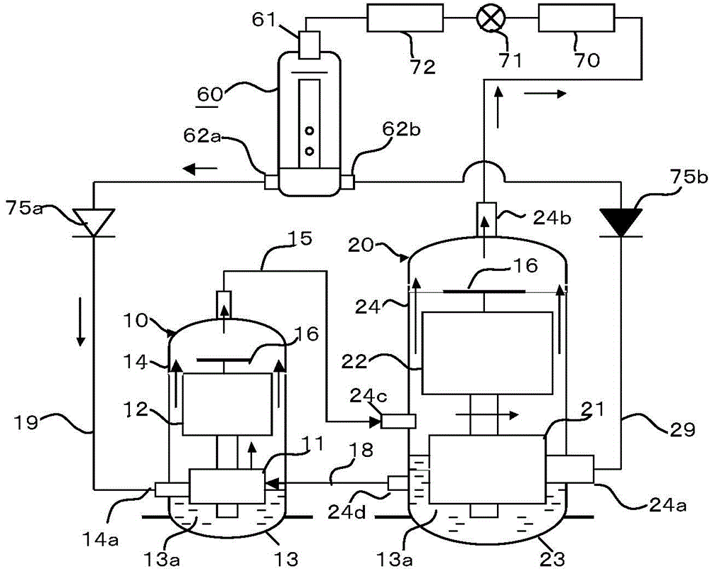
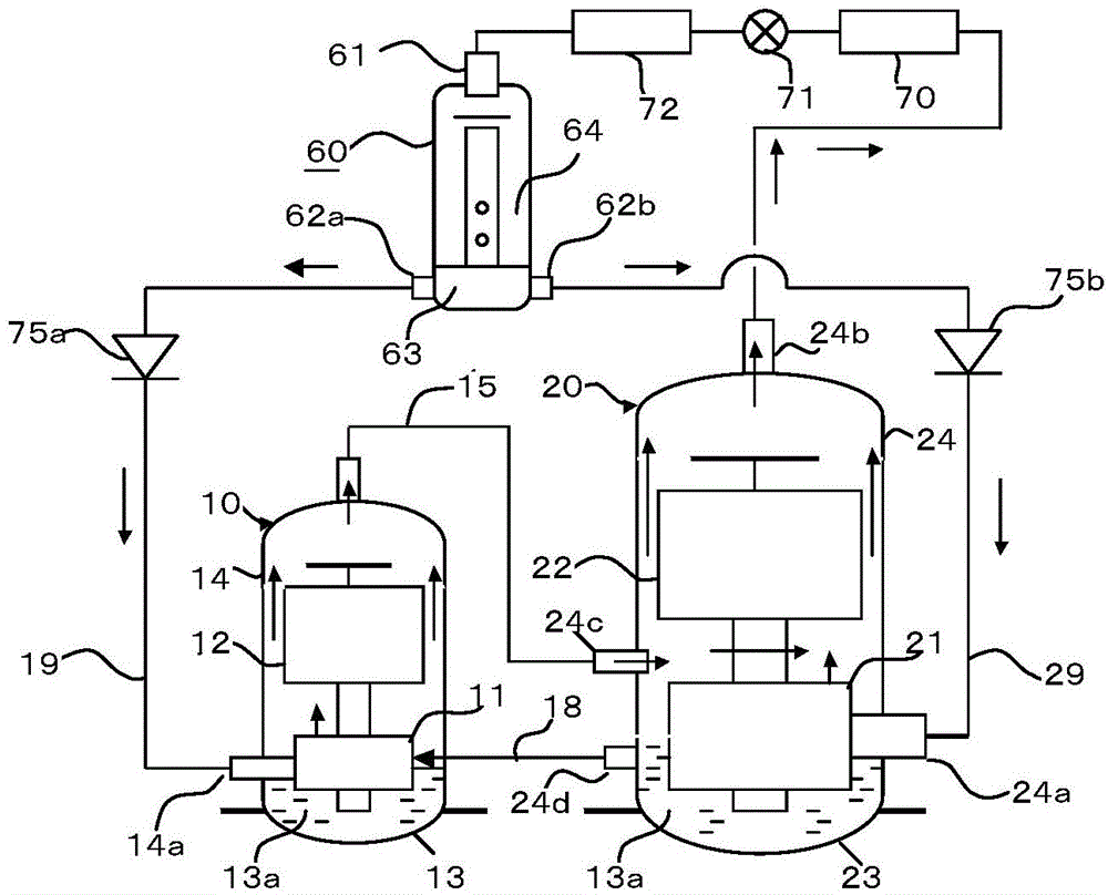
[0058] figure 1 In the illustrated refrigeration cycle, a rotary compressor 10 houses a compression mechanism unit 11 and a motor unit 12 in a casing 14 . Meanwhile, the casing 24 of the rotary compressor 20 accommodates the compression mechanism part 21 and the motor part 22 . In addition, each compressor has an oil storage chamber 13 and an oil storage chamber 23 located at the bottom of the casing, and necessary lubricating oil 13a (hereinafter simply referred to as oil 13a ) is stored therein.
[0059] In general, the oil storage chambers of the rotary compressor range from the height of the center of each compression mechanism unit to the bottom of each casing. However, the oil level during operation often fluctuates up and down. Especially when the compressor is started at a low temperature, a large amount of oil and a large amount of condensed refrigerant will be discharged into the condenser together, so the oil level and oil volume in the oil storage chamber will be...
Embodiment 2
[0103] Figure 4 The illustrated embodiment 2, with respect to the embodiment 1, has added a rotary compressor 30, and there are 3 compressors in total to constitute a refrigeration cycle device. As in the first embodiment, the discharge circuit 25 of the rotary compressor 20 is connected to the connection pipe 34 c of the rotary compressor 30 . The oil injection pipe 28 is connected to the oil discharge pipe 34 d of the rotary compressor 30 and the rotary compressor 10 . All three rotary compressors mentioned above are in operation.
[0104] The high-pressure refrigerant discharged from the rotary compressor 10 is combined with the exhaust refrigerant of the rotary compressor 20 and flows into the rotary compressor 30 . Then, the refrigerant discharged from the rotary compressor 30 is combined and discharged to the condenser 70 from the discharge pipe 34 b. On the other hand, excess oil 13 a in the oil storage chamber 33 returns to the rotary compressor 10 from the oil inj...
Embodiment 3
[0111] Embodiment 3 is a specific application case of embodiment 1 or embodiment 2. Figure 6 The motor unit 12 of the middle and rotary compressors 10 adopts an inverter motor with variable rotation speed, and the rotary compressor 20 adopts a capacity control type compression mechanism unit 21 whose cooling capacity can be varied in two stages.
[0112] In the rotary compressor 10, the cooling capacity is the smallest when the rotational speed of the motor unit 12 is the smallest, and the cooling capacity is the largest when the rotational speed is the highest. Here, the minimum and maximum rotation speeds are 10rps and 120rps, respectively. The cooling capacity obtained at this time is mode A. That is, mode A is variable cooling capacity according to the rotational speed.
[0113]The capacity-controlled compression mechanism part 21 can be implemented using existing technologies, such as the disclosure content of Patent Document 3 (CN201410046931.5). The rotary compressor...
PUM
 Abstract
Description
Claims
Application Information
 - R&D Engineer
- R&D Manager
- IP Professional
- Industry Leading Data Capabilities
- Powerful AI technology
- Patent DNA Extraction
Browse by: Latest US Patents, China's latest patents, Technical Efficacy Thesaurus, Application Domain, Technology Topic, Popular Technical Reports.
© 2024 PatSnap. All rights reserved.Legal|Privacy policy|Modern Slavery Act Transparency Statement|Sitemap|About US| Contact US: help@patsnap.com


