High-voltage power distribution room cooling and dehumidifying energy-saving device

A high-voltage power distribution, cooling and dehumidification technology, applied in the field of cooling and dehumidification of high-voltage power distribution rooms, can solve problems such as short circuit of switchgear, high switch temperature trip, damage to indoor facilities, etc., to reduce energy loss, save air conditioning costs, and reduce use. effect of time

Inactive Publication Date: 2015-09-23
王鹤
View PDF12 Cites 1 Cited by
  • Summary
  • Abstract
  • Description
  • Claims
  • Application Information

AI Technical Summary

Problems solved by technology

[0002] The high-voltage power distribution room has strict requirements on the indoor temperature and humidity. When the indoor temperature is too high, it will cause abnormal operation of the equipment and easily cause the switch to trip due to high temperature. In addition, the humidity in the high-voltage power distribution room is too high. It will cause indoor metal equipment to be damp and rust, switch equipment will cause short circuit, and even damage indoor facilities

Method used


Image

  • High-voltage power distribution room cooling and dehumidifying energy-saving device
  • High-voltage power distribution room cooling and dehumidifying energy-saving device
  • High-voltage power distribution room cooling and dehumidifying energy-saving device

Examples


Embodiment 1

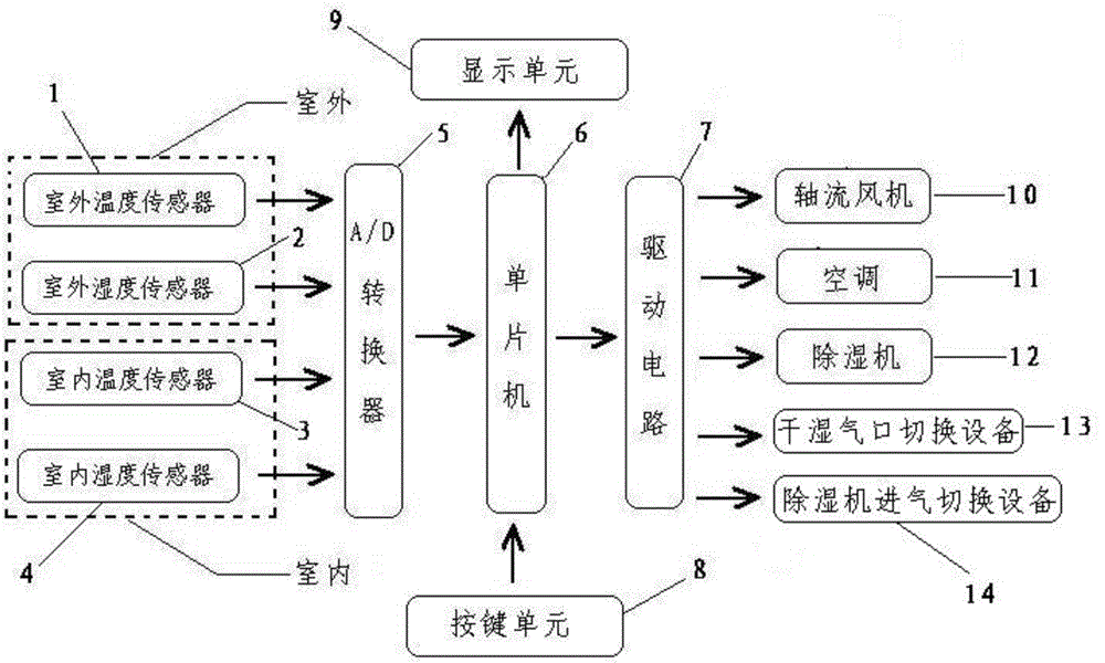
[0035] As shown in the figure, a cooling and dehumidification energy-saving device for a high-voltage power distribution room of this patent includes an outdoor temperature sensor 1, an indoor temperature sensor 3, an outdoor humidity sensor 2, an indoor humidity sensor 4, an A / D converter 5, a single-chip microcomputer 6, Drive circuit 7, key unit 8, display unit 9, axial flow fan 10, air conditioner 11, dehumidifier 12, air outlet, air inlet, inlet and outlet switching device 13 and dehumidifier inlet switching device 14.

[0036] The outdoor temperature sensor 1, the indoor temperature sensor 3, the outdoor humidity sensor 2 and the indoor humidity sensor 4 are all connected to the input end of the A / D converter 5, the output end of the A / D converter 5 is connected to the single chip microcomputer 6, and the output end of the key unit 8 Connect the single-chip microcomputer 6, the single-chip microcomputer 6 is connected to the input terminal of the display unit 9, and the s...

Embodiment 2

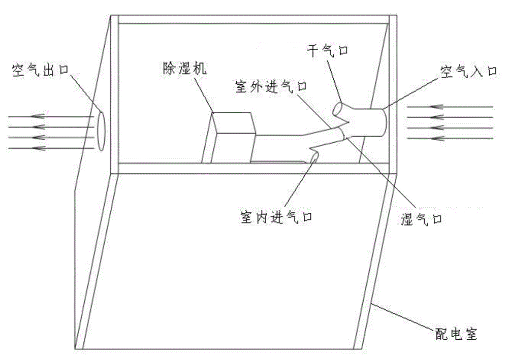
[0048] For a high-voltage power distribution room, the temperature is required to be below 30°C, the humidity is required to be below 40%RH, the temperature margin is 5°C, and the humidity margin is 5%RH. Use this device to control the temperature and humidity of the high-voltage power distribution room. Control; when the outdoor temperature of the high-voltage power distribution is 35°C and the humidity is 50%RH, while the temperature inside the high-voltage power distribution room is 40°C and the humidity is 60%RH, the device first controls the dry and wet air inlet and outlet switching equipment 13 to close Dry air outlet, dehumidifier intake switching device 14 closes the indoor air intake, then starts the explosion-proof axial flow fan 10 to replace the indoor and outdoor air, and at the same time starts the dehumidifier 12 to directly dehumidify the air entering the room. When the indoor and outdoor air temperature balance , then the device controls the explosion-proof ax...


PUM


Abstract

The invention discloses a high-voltage power distribution room cooling and dehumidifying energy-saving device which comprises an outdoor temperature sensor, an indoor temperature sensor, an outdoor humidity sensor, an indoor humidity sensor, an A / D converter, a single-chip microcomputer, a drive circuit, a key unit, a display unit, an axial flow fan, an air conditioner, a dehumidifier, an air outlet, an air inlet, an air input and output switching device and a dehumidifier air inlet switching device. By means of the device, the working time of the axial flow fan, the air conditioner and the dehumidifier can be overall arranged, and energy conservation and consumption reduction are achieved as mush as possible on the premise of ensuring that the indoor temperature and humidity of a high-voltage power distribution room are in a normal state.

Description

technical field [0001] The invention relates to the field of cooling and dehumidification of a high-voltage power distribution room, in particular to a cooling, dehumidification and energy-saving device for a high-voltage power distribution room. Background technique [0002] The high-voltage power distribution room has strict requirements on the indoor temperature and humidity. When the indoor temperature is too high, it will cause abnormal operation of the equipment and easily cause the switch to trip due to high temperature. In addition, the humidity in the high-voltage power distribution room is too high. It will cause indoor metal equipment to be damp and rust, switch equipment will cause short circuit, and even damage indoor facilities. [0003] In the dry weather conditions in the north, the humidity in the high-voltage power distribution room will exceed the humidity requirement only in a very small number of times. Not high enough. [0004] Therefore, we have desi...

Claims


Application Information

Patent Timeline
Patent Type & Authority Applications(China)
IPC IPC(8): F24F11/00
CPCF24F11/30F24F11/62F24F11/77F24F2110/10F24F2110/12F24F2110/20F24F2110/22Y02B30/70
Inventor 岳丽雅范军立王志王晓明
Owner 王鹤
Why Eureka
Try Eureka