Ultrasonic assisted argon arc welding method and auxiliary device with adjustable sound source incidence angle and position
An incident angle, ultrasonic-assisted technology, applied in the direction of arc welding equipment, welding equipment, welding accessories, etc., can solve the problem that the ultrasonic horn and welding torch cannot be synchronized at the same time, the incident angle and position of the ultrasonic sound source cannot be adjusted, etc. problems, to achieve the effect of improving the mechanical properties of the weld metal, uniform and fine structure, and improving the mechanical properties
- Summary
- Abstract
- Description
- Claims
- Application Information
AI Technical Summary
Problems solved by technology
Method used
Image

Examples
Embodiment 1
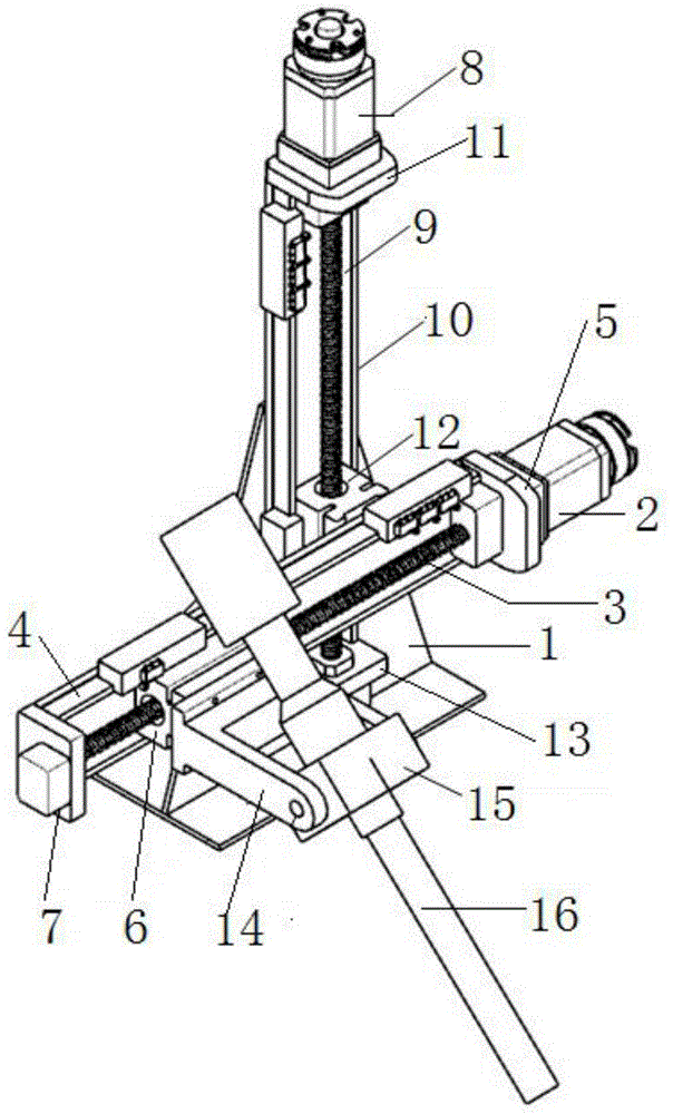
[0057] Such as figure 1 and 2 As shown, an ultrasonic-assisted argon arc welding auxiliary device with adjustable sound source incidence angle and position, including an ultrasonic welding fixture and an ultrasonic follow-up system.
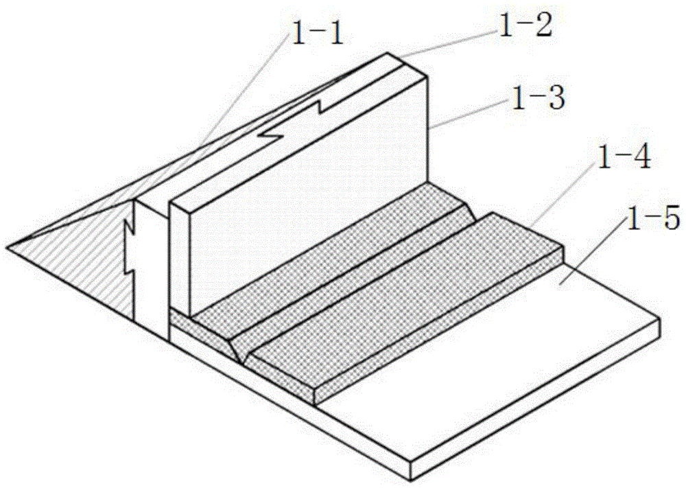
[0058] Wherein, the ultrasonic welding fixture includes an angle-adjustable insert 1-1 with a bevel, an adjustable distance pad 1-2, a height-adjustable pressure block 1-3 and a base 1-5, and the fixture is used for ultrasonic Assisted argon tungsten arc welding with adjustable sound source angle and position.
[0059] The vertical surface of the angle-adjustable insert 1-1 is flexibly connected to the first side of the distance-adjustable pad 1-2. The specific connection method is: the vertical surface of the angle-adjustable insert 1-1 is provided with For the dovetail groove, the first side of the distance-adjustable cushion block 1-2 is provided with a convex dovetail block matched with the dovetail groove, so as to realize the fixing of th...
Embodiment 2
[0070] Using the above-mentioned auxiliary device, the non-ferrous metal plate to be welded is 180*100*6mm copper plate for ultrasonic-assisted tungsten argon arc welding, and the welding steps are as follows:
[0071] (1) Make a V-shaped groove on the copper plate, and use an ultrasonic welding fixture to clamp the copper plate, so that the non-groove side of the copper plate is in close rigid contact with the base 1-5 of the ultrasonic welding fixture, as figure 1 shown. Then fix the copper plate and the ultrasonic welding fixture on the welding platform.
[0072] (2) Replace the angle-adjustable insert 1-1, the angle between the slope of the angle-adjustable insert 1-1 and its bottom surface is 90°, so that the sound wave is incident in the form of a transverse wave, and the distance between the adjustable pad 1-2 The thickness is 10mm, and then fixed with a U-shaped fixture to realize the tight and rigid contact between the upper, lower and side surfaces of the ultrasonic...
Embodiment 3
[0079] Use the above-mentioned auxiliary device to perform ultrasonic-assisted argon tungsten arc welding on the red copper plate to be welded with a non-ferrous metal plate size of 180*100*6mm. The welding steps are as follows:
[0080] (1) Make a V-shaped groove on the copper plate, and use an ultrasonic welding fixture to clamp the copper plate, so that the non-groove side of the copper plate is in close rigid contact with the base 1-5 of the ultrasonic welding fixture, as figure 1 shown. Then fix the copper plate and the ultrasonic welding fixture on the welding platform.
[0081] (2) Remove the angle adjustable insert 1-1, so that the ultrasonic horn 16 is directly applied on the upper surface of the distance adjustable pad 1-2, and the thickness of the distance adjustable pad 1-2 is 10mm, so that the sound wave Incidence in the form of longitudinal waves.
[0082] (3) Clamp the ultrasonic horn 16 on the ultrasonic servo system, adjust the height of the welding fixture ...
PUM
| Property | Measurement | Unit |
|---|---|---|
| thickness | aaaaa | aaaaa |
| thickness | aaaaa | aaaaa |
Abstract
Description
Claims
Application Information
 - R&D
- Intellectual Property
- Life Sciences
- Materials
- Tech Scout
- Unparalleled Data Quality
- Higher Quality Content
- 60% Fewer Hallucinations
Browse by: Latest US Patents, China's latest patents, Technical Efficacy Thesaurus, Application Domain, Technology Topic, Popular Technical Reports.
© 2025 PatSnap. All rights reserved.Legal|Privacy policy|Modern Slavery Act Transparency Statement|Sitemap|About US| Contact US: help@patsnap.com