
Ring-removing mechanism for single-head large-cylinder-diameter nodular cast iron piston ring

A technology of nodular cast iron and piston rings, which is applied in the field of runner separation mechanisms, can solve the problems of high labor intensity, deformation of piston ring blanks, high scrap rate, etc., and achieve simple and reliable mechanism structure, convenient ring removal work, and reduced labor intensity effect

Inactive Publication Date: 2015-09-23
ASIMCO SHUANGHUAN PISTON RING YIZHENG
View PDF0 Cites 2 Cited by
  • Summary
  • Abstract
  • Description
  • Claims
  • Application Information

AI Technical Summary

Problems solved by technology

[0002] At present, after the general piston ring casting process, the operator can easily separate the piston ring blank from the runner by hand or auxiliary tools, but for the single-head large-bore ductile iron piston ring, the traditional ring removal scheme cannot or is not easy The blank and the runner are separated, and the staff generally use special methods to carry out the de-ring work of such piston ring castings, such as hitting with a sledgehammer. The biggest disadvantage of this method is that it is easy to cause deformation of the piston ring blank, resulting in high waste products rate, and the labor intensity of workers is relatively high

Method used


Image

  • Ring-removing mechanism for single-head large-cylinder-diameter nodular cast iron piston ring

Examples


Embodiment Construction

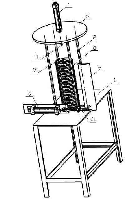
[0008] like figure 1 As shown, the present invention vertically fixes four support rods 2 on the workbench 1, supports a circular cover 3 arranged horizontally above the four support rods 2, and connects a vertical cover 3 at the center of the cover 3. The telescopic rod 41 of the vertical impact cylinder 4 is inserted into the center hole of the cover plate 3 .

[0009] A rear baffle 5 is vertically arranged inside the space surrounded by four support rods 2 , and the lower end of the rear baffle 5 is fixedly welded on the workbench 1 .

[0010] A horizontal compression cylinder 6 is also fixed on the workbench 1, and a front baffle 7 is fixedly connected to the end of the telescopic rod 61 of the horizontal compression cylinder 6.

[0011] When the horizontal compression cylinder 6 is tightened, the telescopic rod 61 brings back the front baffle 7, so that the front baffle 7 and the rear baffle 5 embrace the piston ring arranged between the front baffle 7 and the rear baffl...


PUM


Abstract

The invention discloses a ring-removing mechanism for a single-head large-cylinder-diameter nodular cast iron piston ring, and belongs to the technical field of piston ring machining. A workbench is vertically provided with at least three supporting rods in a fixed manner, and the supporting rods support one horizontal cover plate. The center of the cover plate is connected with a telescoping rod which passes through a vertical impact cylinder in a central hole of the cover plate. An inner side of a space formed by the enclosing of the supporting rods is provided with a rear baffle plate in a vertical manner. The workbench is also fixedly provided with a horizontal clamping cylinder, and the tail end of the telescoping rod is fixedly connected with a front baffle plate. When the horizontal clamping cylinder shrinks, the front baffle plate and the rear baffle plate surround a piston ring blank disposed between the front and rear baffle plates. The mechanism provided by the invention can enable the ring removal of the single-head large-cylinder-diameter nodular cast iron piston ring to be completed conveniently and reliably, reduces the rejection rate, and reduces the labor intensity of workers.

Description

technical field [0001] The invention belongs to the technical field of piston ring processing, in particular to a mechanism for separating a piston ring blank from a runner therein. Background technique [0002] At present, after the general piston ring casting process, the operator can easily separate the piston ring blank from the runner by hand or auxiliary tools, but for the single-head large-bore ductile iron piston ring, the traditional ring removal scheme cannot or is not easy The blank and the runner are separated, and the staff generally use special methods to carry out the de-ring work of such piston ring castings, such as hitting with a sledgehammer. The biggest disadvantage of this method is that it is easy to cause deformation of the piston ring blank, resulting in high waste products rate, while the labor intensity of workers is relatively high. Contents of the invention [0003] The purpose of the present invention is to overcome the deficiencies of the pri...

Claims


Application Information

Patent Timeline
IPC IPC(8): B22D31/00
Inventor 殷从伟周伟张胜利倪亚超
Owner ASIMCO SHUANGHUAN PISTON RING YIZHENG
Learn More