Actuator, motor vehicle with such an actuator and method for operating the actuator

A technology of actuators and mechanical movement, applied in the field of actuators, can solve problems such as expensive control costs, and achieve the effect of solving the stuck problem

Active Publication Date: 2018-08-31
AUDI AG
View PDF4 Cites 0 Cited by
  • Summary
  • Abstract
  • Description
  • Claims
  • Application Information

AI Technical Summary

Problems solved by technology

[0009] The various devices and methods known from the prior art for eliminating sticking of the actuator mostly require expensive controls

Method used


Image

  • Actuator, motor vehicle with such an actuator and method for operating the actuator
  • Actuator, motor vehicle with such an actuator and method for operating the actuator

Examples


Embodiment Construction

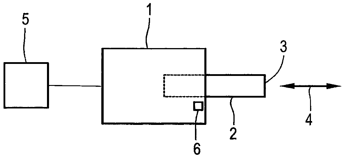
[0021] exist figure 1 An actuator 1 is shown in , which is designed to convert an electrical signal into a mechanical movement. The actuator 1 comprises a piston 2 , the free end 3 of which protrudes from the housing of the actuator 1 . The piston 2 is movable in the direction indicated by the double arrow 4 . The movement of the piston 2 is effected electromechanically, whereby the piston 2 can be positioned. Another component can be arranged on the free end 3 or the movement of the piston 2 can bring about an action, for example opening or closing a valve or moving or positioning another component.

[0022] The actuator 1 has an electromechanical drive, which in figure 1 not shown in detail. The control unit 5 controls the actuator 1 connected thereto, in which it controls the supply voltage for the electromechanical drive. Displacement sensor 6 arranged in actuator 1 is designed to detect the position of piston 2 and to generate a sensor signal. The evaluation of the ...


PUM


Abstract

The invention relates to an actuator (1) which is designed to convert electrical signals into mechanical movements, the actuator has a disengagement function for eliminating functional faults, such as jamming, wherein a device is provided for The increased voltage is supplied to the actuator (1) when the disengagement function is activated.

Description

technical field [0001] The invention relates to an actuator, which is designed to convert an electrical signal into a mechanical movement, and which has a disengagement function for troubleshooting malfunctions, such as jamming. Background technique [0002] The term actuator used in this application generally refers to a regulator or adjusting element, which can be used preferably in a motor vehicle to convert an electrical signal into a movement. This movement of the components enables adjustment of the movable member to perform a specific, desired function. Adjustment can take place, for example, as a movement or rotation. Actuators of this type are used in large numbers in motor vehicles to carry out mechanical adjustment movements, for example, on internal combustion engines or their associated units or on chassis or bodywork. [0003] Actuators generally have an electromechanical drive, which generates an electromagnetic field, which exerts a force on the movable or ...

Claims


Application Information

Patent Timeline
Patent Type & Authority Patents(China)
IPC IPC(8): B60R16/00F02D41/20F02D11/10
CPCF02D41/20H01F7/1844H01F2007/185F02D2011/108B60R16/02
Inventor M·基尔格
Owner AUDI AG
Why Eureka
Try Eureka