Pure countercurrent compact type pipe folding economizer

A compact, economizer technology, used in tubular elements, fluid circulation arrangements, evaporators/condensers, etc., which can solve the problem of low overall heat exchange efficiency of economizers, low flow rate of working medium on the shell side, and large tube side space, etc. problems, to achieve the effect of fully utilizing the heat exchange area, matching the heat exchange process, and compacting the shell side space

Inactive Publication Date: 2015-09-16
GUANGZHOU INST OF ENERGY CONVERSION - CHINESE ACAD OF SCI
View PDF4 Cites 0 Cited by
  • Summary
  • Abstract
  • Description
  • Claims
  • Application Information

AI Technical Summary

Problems solved by technology

The economizers currently used in the industry are generally traditional flooded heat exchangers. The quality and flow rate of the shell side and the tube side of this type of heat exchanger are almost equal, but a small amount of refrigerant liquid is used in the shell side, and the refrigerant vapor is used in the tube side. The volume ratio of the two is (3-6): 1, that is, for the design of this type of traditional heat transfer tube heat exchanger, the space of the shell side is generally much larger than the space of the tube side, which leads to the flow rate of the working fluid in the shell side It is very low, so that the total heat transfer efficiency of the whole economizer is not high, and the volume is large, especially for the environment with limited space such as ships and automobiles, a small and compact economizer is urgently needed
For the economizer, the efficient operation of the economizer can only be achieved by making the volume of the tube side larger than the volume of the shell side, and the original manufacturing process cannot realize the space of the tube side larger than the space of the shell side, which is due to the original heat transfer tube. The diameter does not change, and the spacing of the heat transfer tubes at the tube sheet is always 1.25 times the diameter of the heat transfer tubes

Method used


Image

  • Pure countercurrent compact type pipe folding economizer
  • Pure countercurrent compact type pipe folding economizer
  • Pure countercurrent compact type pipe folding economizer

Examples


Embodiment

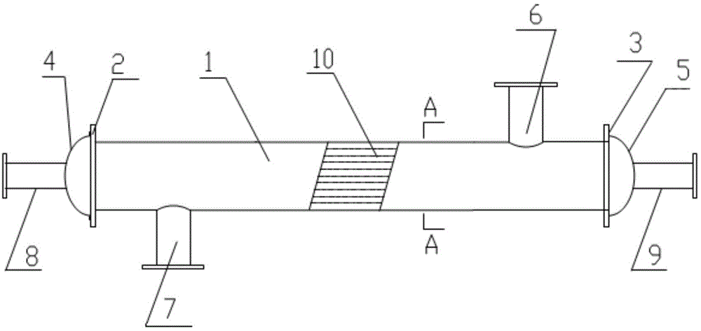
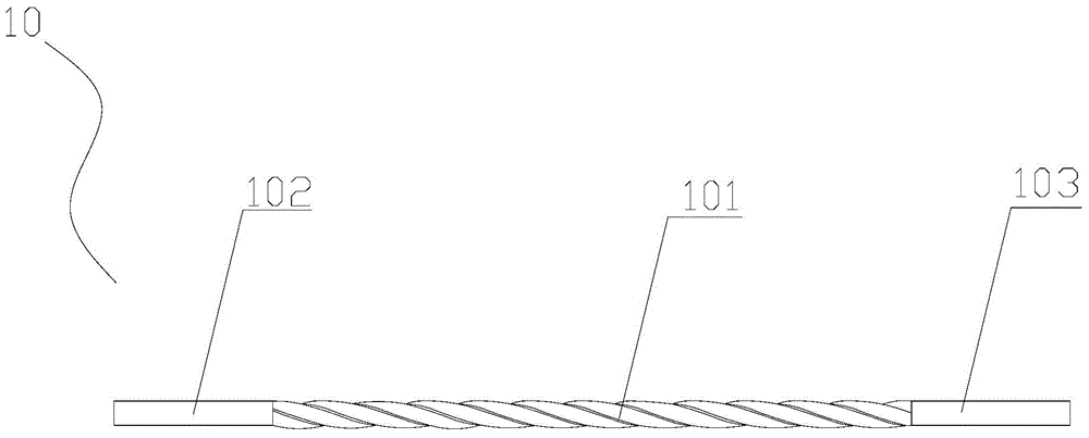
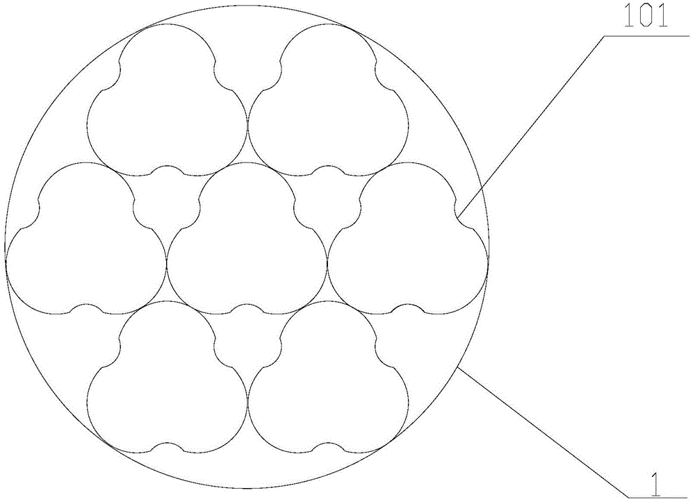
[0030] Please refer to figure 1 As shown, the pure countercurrent compact stacked tube economizer includes a shell 1, and the two ends of the shell 1 are respectively closed by a tube plate 2 and a tube plate 3 to form an accommodating space, and the shell 1 is installed with A plurality of heat exchange tubes 10, the outer sides of the tube sheet 2 and the tube sheet 3 are respectively fixedly connected to the head 4 and the head 5, and one end of the heat exchange tube 10 is welded to the tube sheet 2, and is fixedly connected to the sealing head 4 through the head 4. The tube side inlet 8 on the head 4 is connected, and the other end of the heat exchange tube 10 is welded on the tube sheet 3 , and communicates with the tube side outlet 9 fixedly connected to the head 5 through the head 5 . The upper and lower sides of the shell 1 are respectively fixedly connected with a shell-side inlet 6 and a shell-side outlet 7 communicating with the accommodation space, wherein the she...


PUM


Abstract

The invention discloses a pure countercurrent compact type pipe folding economizer. The economizer comprises a shell, wherein the two ends of the shell are respectively closed by a first pipe plate and a second pipe plate to form an accommodating space; multiple heat exchange tubes are mounted in the shell, and comprise a heat transfer pipe and first and second round pipes connected to the two ends of the heat transfer pipe; the first round pipe, the heat transfer pipe and the second round pipe are integrally molded, and are equal in perimeters of cross sections; the adjacent heat exchange tubes realize the point contact through projection parts on the heat transfer pipe to form a self-support structure; and gaps are correspondingly formed between adjacent two contact points of the adjacent heat exchange tubes to form a netty channel in the accommodating space. The economizer achieves effective size control of a tube shell pass space through changing the flattening rate and the twisting rate of the deformed heat exchange tubes, so that the shell pass space is more compact, the flowing speed of shell pass refrigerant liquid is accelerated, the tube shell pass heat exchange process is more matched, and the volume of the economizer is reduced.

Description

technical field [0001] The invention relates to thermal equipment, in particular to a pure countercurrent compact stacked tube economizer. Background technique [0002] Refrigeration units are widely used in various fields. The economizer is added to the refrigeration unit. Its purpose is to exchange heat between the high-temperature and high-pressure refrigerant liquid and the low-temperature and low-pressure refrigerant vapor to achieve supercooling of the refrigerant liquid and refrigerant vapor The purpose of overheating, thereby increasing the cooling capacity of the entire system. The economizers currently used in the industry are generally traditional flooded heat exchangers. The quality and flow rate of the shell side and the tube side of this type of heat exchanger are almost equal, but a small amount of refrigerant liquid is used in the shell side, and the refrigerant vapor is used in the tube side. The volume ratio of the two is (3-6): 1, that is, for the design ...

Claims


Application Information

Patent Timeline
Patent Type & Authority Applications(China)
IPC IPC(8): F25B39/00F28F1/02F25B41/00F25B41/40
CPCF25B40/00F28F1/02
Inventor 朱冬生刘世杰胡明军綦尤训
Owner GUANGZHOU INST OF ENERGY CONVERSION - CHINESE ACAD OF SCI
Why Eureka
Try Eureka