Radial guide blade structure with streamline structure

A technology of radial guide vanes and guide vanes, which is applied to components of pumping devices for elastic fluids, mechanical equipment, non-variable pumps, etc. Problems such as too large placement angle, to achieve the effect of not easy to vortex, smooth flow path, and reduce circulation

Active Publication Date: 2015-09-16
HEFEI GENERAL MACHINERY RES INST
View PDF7 Cites 5 Cited by
  • Summary
  • Abstract
  • Description
  • Claims
  • Application Information

AI Technical Summary

Problems solved by technology

At present, the defects of the above-mentioned traditional radial guide vanes are as follows: First, due to the insufficient structural design of the transition section in the flow channel, there are many obstructed surfaces in the flow channel, and due to the poor control of the fluid flow state and the influence of the top clearance circulation, the fluid often interacts with each other in this section. Collision, passive change of direction, considerable energy loss
Secondly, the anti-guide vanes on the traditional radial guide vanes are all single-diameter single-arc-shaped linear blades. The shape of this single-arc anti-guide vane is too simple, and the placement angle of the blade is often too large, which is poorly consistent with the streamline. The flow state of the fluid is disordered and complex, and it is easy to form a vortex, thereby further losing the kinetic energy of the fluid
Through CFD simulation calculation, the energy loss in the guide vane even accounts for about 13% of the work done by the impeller, which greatly affects the actual working efficiency of the guide vane

Method used


Image

  • Radial guide blade structure with streamline structure
  • Radial guide blade structure with streamline structure
  • Radial guide blade structure with streamline structure

Examples


Embodiment Construction

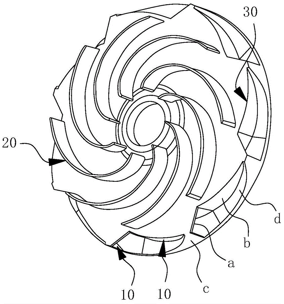
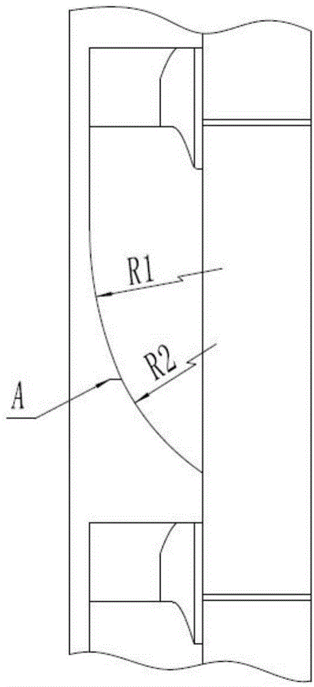
[0019] For ease of understanding, combined here Figure 2-4 Concrete structure of the present invention and implementation effect are further described as follows:

[0020] The specific structure of the present invention is as Figure 2-4 As shown, it is located in the annular space of the radial guide vane, at the position A where the tip of the positive guide vane 10 is located, that is, at the transition section, and the guide surface d for arc transition is set to make the fluid change direction smoothly. The arc where the diversion surface d is located changes according to the law that the radius of curvature gradually decreases from the starting point to the end point of the arc, and the arc can be simplified into two or more arcs at the same time. And as figure 2 and Figure 4 As shown, the anti-guide vane 20 adopts the method of conformal transformation and is designed according to the streamline. The curvature radius of the blade bone line gradually decreases from...


PUM


Abstract

The invention belongs to the field of guide blade structure design applied to sectional multi-stage centrifugal pumps, and particularly relates to a radial guide blade structure with a streamline structure. Forward guide blades are arranged on the disc face of a guide blade disc, backward guide blades are arranged on the back face of the guide blade disc, a forward flow pass and a backward flow pass are formed between every adjacent forward guide blade and backward guide blade. A notch portion penetrating through a disc body is formed in an outlet of the forward flow pass of the guide blade disc, the disc face, where the notch portion is located, of the guide blade disc, the outer blade faces of the forward guide blades, the peripheral surface of the guide blade disc and a guide face arranged opposite to the disc face, where the notch portion is located, of the guide blade disc jointly form a transition cavity, the appearance of the guide face is of a cambered surface structure, the center of curvature of the guide face of the cambered surface structure is located at the end, where the backward guide blades are located, of the guide blade disc, and the curvature radius of the guide face of the cambered surface structure from a water inlet end of the transition cavity to a water outlet end of the transition cavity is reduced gradually. The radial guide blade structure with the streamline structure can reduce ring currents, fluid collision and vortex situations generated in the transition section, energy loss can be restricted effectively, and working efficiency is higher.

Description

technical field [0001] The invention belongs to the field of guide vane structure design applied to segmental multistage centrifugal pumps, in particular to a radial guide vane structure with a streamline structure. Background technique [0002] For segmental multi-stage pumps, guide vanes are needed for the transition between stages, so that the fluid can flow smoothly from one stage to the next stage, so as to realize energy conversion and recovery, and reduce energy loss during flow. Traditional segmental multistage pump guide vanes are generally divided into two types: radial guide vanes or flow channel guide vanes. Compared with the flow channel guide vane with complex structure and immature manufacturing process, the design technology of radial guide vane has been finalized, and it is more widely used because of the mature casting process and high cost performance. The flow path of traditional radial guide vanes such as figure 1 As shown, it is composed of the follow...

Claims


Application Information

Patent Timeline
IPC IPC(8): F04D29/44F04D29/66
Inventor 操松林薛胜雄韩彩红任启乐苏吉鑫庞雷陈正文王永强
Owner HEFEI GENERAL MACHINERY RES INST
Why Eureka
Try Eureka