
Movable jaw mounting assembly

一种安装组件、活动颚的技术,应用在谷物处理等方向,能够解决增加维护更换磨损件等问题

Active Publication Date: 2015-09-09
SANDVIK INTPROP AB
View PDF19 Cites 6 Cited by
  • Summary
  • Abstract
  • Description
  • Claims
  • Application Information

AI Technical Summary

Problems solved by technology

[0008] However, conventional retract assemblies that allow adjustment of the CSS or enable dunnage set mode include relatively complex retract actuator and hydraulic jack arrangements that perform separate functions
Traditional systems often include many components and moving parts, which increases the frequency of maintenance and the need to replace worn parts

Method used


Image

  • Movable jaw mounting assembly
  • Movable jaw mounting assembly
  • Movable jaw mounting assembly

Examples


Embodiment Construction

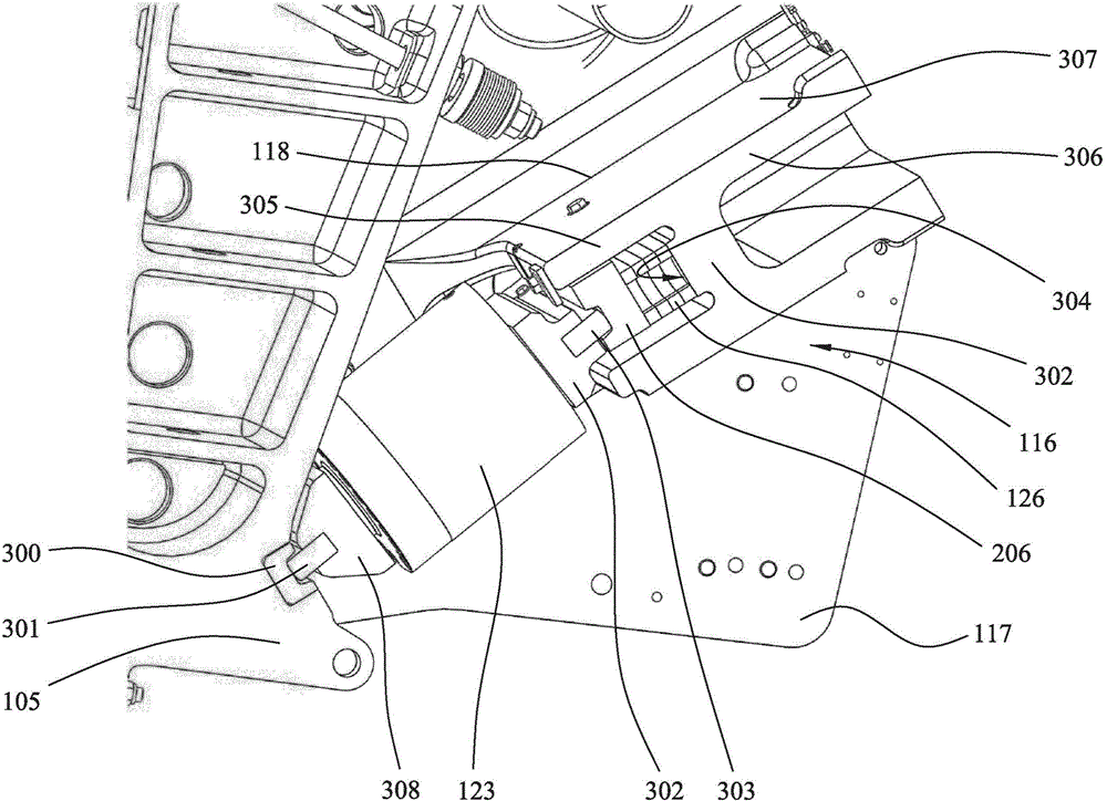
[0033] refer to figure 1, the jaw crusher 100 includes a main frame 102 on which a movable jaw 105 and a substantially fixed jaw 104 are mounted. The movable jaw 105 is mounted eccentrically at a rotatable shaft 107 (extending from below the end cap 109 ) and is positioned apart from and opposite the fixed jaw 104 . The orientations of the fixed jaw 104 and the movable jaw 105 relative to each other converge along their respective lengths such that the spacing between the crushing surface 111 of the fixed jaw 104 and the corresponding crushing surface 110 of the movable jaw 105 decreases in the downward longitudinal direction . A suitable wear plate 113 is removably attached to the crushing face 111 of the fixed jaw 104 and a corresponding wear plate 114 is removably attached to the crushing face 110 of the movable jaw 105 . The main frame 102 includes two opposing frame walls that support a front frame end 108 that is aligned substantially perpendicular to the frame wall 10...


PUM


Abstract

A movable jaw mounting assembly to provide adjustment of the close side setting (CSS) of a movable jaw (105) and to act as a retraction assembly or assist with retraction. The assembly comprises a pair of linear actuators (122) that are coupled between a force transmission wall (302) of a support frame (116) and a region of the toggle unit so as to move the toggle unit towards and away from the force transmission wall end to allow insertion and removal of spacers and / or shims (126).

Description

technical field [0001] The present invention relates to a mounting assembly for a movable jaw of a jaw crusher, and in particular but not exclusively to a device configured to displace a switching unit formed by a force-transmitting wall to allow adjustment in the movable jaw The working distance between the movable jaw and the fixed jaw retracts the assembly. Background technique [0002] A jaw crusher unit generally includes a fixed jaw and a movable jaw that together define a crushing zone. The drive mechanism is operable to swing the movable jaw back and forth to break material in the crushing zone. [0003] The crushing zone typically converges towards its lower discharge end so that the breakable material fed to the wider upper end of the crushing zone can fall downwards under the force of gravity while being subjected to repeated cycles of crushing in response to the cyclic movement of the movable jaw sports. The crushed material is then discharged by gravity throu...

Claims


Application Information

Patent Timeline
Patent Type & Authority Applications(China)
IPC IPC(8): B02C1/02
CPCB02C1/025
Inventor 约翰·斯文松马滕·林德贝里
Owner SANDVIK INTPROP AB
Learn More