Motor control device and electric power steering device

A motor control and motor technology, applied in control devices, power steering mechanisms, electric steering mechanisms, etc., can solve problems such as torque ripple and motor output torque fluctuations

Active Publication Date: 2015-09-09
JTEKT CORP
View PDF6 Cites 16 Cited by
  • Summary
  • Abstract
  • Description
  • Claims
  • Application Information

AI Technical Summary

Problems solved by technology

[0006] However, in the motor control device described in Japanese Patent Application Laid-Open No. 2006-320122, if the current command value fluctuates, the dead time compensation value also fluctuates, resulting in fluctuations in the output torque of the motor, that is, torque ripple.

Method used


Image

  • Motor control device and electric power steering device
  • Motor control device and electric power steering device
  • Motor control device and electric power steering device

Examples


Embodiment Construction

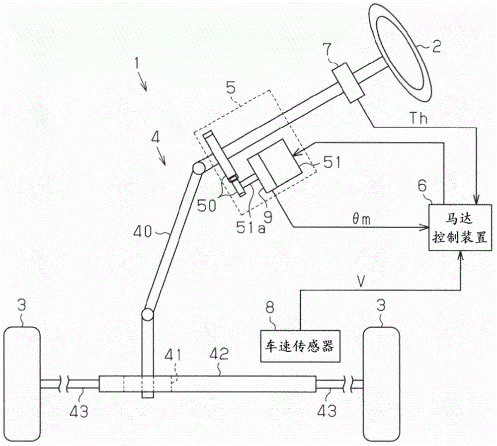
[0031] One embodiment of the motor control device will be described below. First, an outline of an electric power steering device equipped with a motor control device according to the present embodiment will be described.

[0032] Such as figure 1 As shown, the electric power steering system 1 includes a steering mechanism 4 that steers the steering wheels 3 based on the driver's operation of the steering wheel 2 , and an assist mechanism 5 that assists the driver's steering operation.

[0033] The steering mechanism 4 includes a steering shaft 40 connected to the steering wheel 2 , and a rack shaft 42 connected to the lower end of the steering shaft 40 via a rack-and-pinion mechanism 41 . In the steering mechanism 4 , when the steering shaft 40 rotates as the driver operates the steering wheel 2 , the rotational motion is converted into an axial reciprocating linear motion of the rack shaft 42 via the rack and pinion mechanism 41 . The axial reciprocating linear motion of t...


PUM


Abstract

A motor control device includes a motor drive circuit and a microcomputer that controls the drive circuit. The microcomputer generates a control signal on the basis of duty command values Du, Dv, and Dw to control the drive circuit. The microcomputer includes a dead time compensation section 87 that corrects the duty command values Du, Dv, and Dw on the basis of dead time compensation values Ddu, Ddv, and Ddw. The dead time compensation section 87 includes a basic compensation value computation section 92 that computes a basic compensation value Dd as a fundamental value of the dead time compensation values Ddu, Ddv, and Ddw, and a filter section 93 that performs a filtering process corresponding to a low-pass filter on the basic compensation value Dd. The dead time compensation section 87 sets the dead time compensation values Ddu, Ddv, and Ddw on the basis of an output value ± from the filter section 93.

Description

[0001] This application claims priority from Japanese Patent Application No. 2014-045228 filed on March 7, 2014, the entire contents of which are hereby incorporated by reference. technical field [0002] The present invention relates to a motor control device and an electric power steering device. Background technique [0003] A motor control device used in an electric power steering device or the like includes a drive circuit for driving the motor, and a microcomputer for controlling the drive of the motor via the drive circuit. A drive circuit for driving a three-phase motor is constituted by, for example, an inverter circuit. The drive circuit has an arm composed of a pair of switching elements connected in series as a basic unit, and is constituted by connecting three arms corresponding to each of the motors in parallel. A motor control device detects a current supplied to a motor by a current sensor, and calculates a voltage command value by performing current feedback...

Claims


Application Information

Patent Timeline
Patent Type & Authority Applications(China)
IPC IPC(8): H02P23/04B62D5/04
CPCH02P27/08H02P21/00H02M2001/385B62D5/00B62D5/046B60L15/025B60L15/20B60L2240/12B60L2240/423B60L2240/427B60L2240/429B60L2240/80B60L2270/142B60L2270/145H02P21/50Y02T10/72Y02T10/64H02M1/385B62D5/0472B60W10/00
Inventor 三鸭悟小池步
Owner JTEKT CORP
Why Eureka
Try Eureka