
Microstrip array circularly-polarized focusing antenna

A technology for focusing antennas and microstrip arrays, applied in the direction of antennas, antenna arrays, antenna grounding switch structures, etc., can solve the problems of unsatisfactory focusing effects, achieve enhanced focusing effects, good focusing effects, and low side lobes

Inactive Publication Date: 2015-09-09
NANJING UNIV OF INFORMATION SCI & TECH
View PDF8 Cites 8 Cited by
  • Summary
  • Abstract
  • Description
  • Claims
  • Application Information

AI Technical Summary

Problems solved by technology

[0003] M. Bogosanovic proposed an antenna design with equal amplitude and different phases, that is, the phase satisfies the quadratic spherical wave distribution, while the amplitude remains unchanged. From the experimental results, the antenna is transmitted in the form of linear polarization, and The focus effect is not very good

Method used


Image

  • Microstrip array circularly-polarized focusing antenna
  • Microstrip array circularly-polarized focusing antenna
  • Microstrip array circularly-polarized focusing antenna

Examples


Embodiment Construction

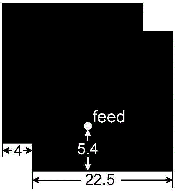
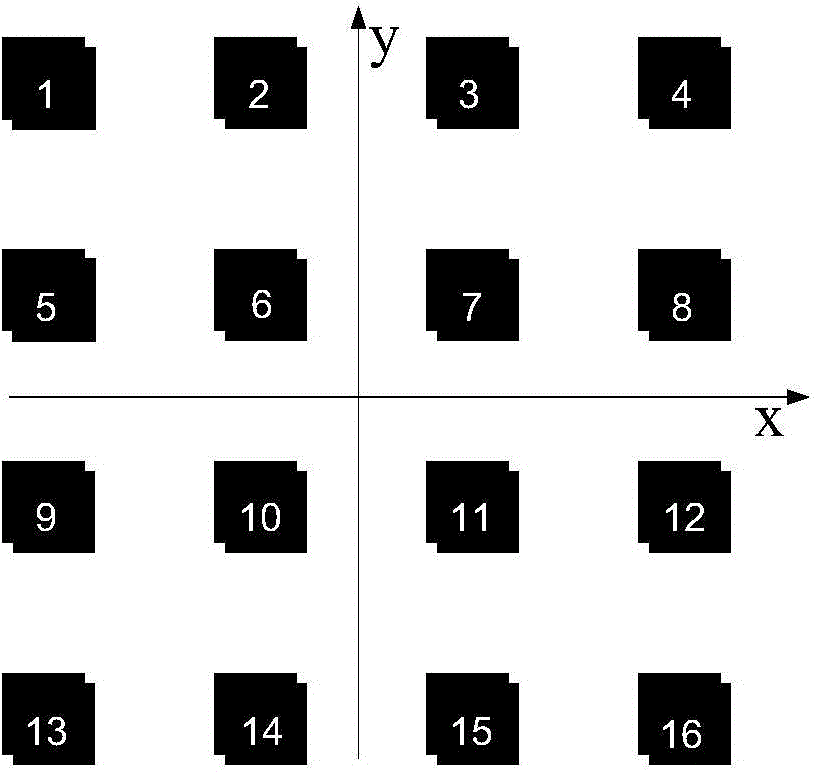
[0028] In order to focus the energy of the transmitting antenna at the position of the receiving antenna, the wireless power transmission system of the present invention adopts the design of the antenna array in a manner of maximizing power transmission. First refer to figure 1 Design a single circularly polarized antenna unit. The circularly polarized antenna unit is a 26.5mm*26.5mm square patch. Two 4mm square cut corners are dug out in the upper left corner and lower right corner respectively. The feed point is located at at the position directly below the center of the patch. then follow figure 2 According to the linear arrangement of 4*4 equal intervals, the unit spacing is 0.5λ, and a single circularly polarized antenna is placed at the expected focus position. According to the method of maximizing power transmission, the size of the antenna unit is obtained through optimization calculation. According to the relevant knowledge of the transmission line. Optimize the d...


PUM

PropertyMeasurementUnit
Frequencyaaaaaaaaaa

Abstract

The invention discloses a microstrip array circularly-polarized focusing antenna. The antenna comprises two dielectric substrates, antenna elements and a feed network. The two dielectric substrates are both made of FR-4 and stacked, the antenna elements is arranged on the upper surface of the upper dielectric substrate; the metal radiation patch and the feed network share a metal grounding surface, and a contact surface is provided for the two dielectric substrates; and the feed network is arranged on the lower surface of the lower dielectric substrate. The circularly-polarized focusing antenna fulfills the purpose of focusing, has good focusing effect, good circular polarization property, good matching and high transmission efficiency, achieves a good focusing effect and enhances the anti-interference performance at the same time.

Description

technical field [0001] The invention belongs to the field of microstrip planar focusing antennas, and relates to a novel circular polarization focusing antenna design, which achieves the focusing effect in the form of circular polarization. Background technique [0002] In order to ensure that the electromagnetic wave energy does not spread during space transmission, the electromagnetic wave must be able to focus to the receiving device like light. From the analogy of light focusing, we know that in order to focus the electromagnetic wave, the phase of the aperture of the transmitting antenna must be spherically distributed. In the early 1960s, Goubao, Shermen, Borigiotti and others did a lot of work on the focusing of aperture antennas, and established the theoretical basis for electromagnetic wave energy transmission. The advantage of microwave as a means of power transmission is that it realizes wireless power transmission, which has practical value in many occasions. Th...

Claims


Application Information

Patent Timeline
IPC IPC(8): H01Q1/38H01Q1/50H01Q21/00
Inventor 文舸一江玉海杨凌升
Owner NANJING UNIV OF INFORMATION SCI & TECH
Learn More