
Petroleum drilling and production equipment, iron roughneck and clamp body

A technology of iron driller and pliers, which is applied to drilling equipment, earthwork drilling, drill pipes, etc. It can solve the problems of low work efficiency, easy generation of lateral force, short punching stroke of the punching cylinder group, etc., and achieves the above High breakout efficiency, large make-up and breakout angle, and good clamping force

Active Publication Date: 2015-09-09
HUNAN SANY PETROLEUM TECH
View PDF10 Cites 12 Cited by
  • Summary
  • Abstract
  • Description
  • Claims
  • Application Information

AI Technical Summary

Problems solved by technology

[0004] In the prior art, the punching pliers generally provide punching torque through the punching cylinder group, so that the punching pliers rotate at a certain angle relative to the clamping pliers. The punching cylinder group has a short punching stroke, and a single punching can only rotate 27° Left and right, the work efficiency is low. In addition, most iron drillers do not have the function of loading and unloading drill bits at present, and other special equipment must be used when loading and unloading drill bits.
[0005] In addition, the clamping pliers and punching pliers generally consist of a cover plate, a bottom plate and a side plate to form a main frame, and there are two symmetrical clamping cylinders inside. The cylinder end of the clamping cylinder is fixed on the side plate, and the piston rod can The cylinder is free to expand and contract, and the end of the cylinder is equipped with a tooth plate, and the piston rods of the two clamping cylinders that are symmetrically arranged extend out. Be prepared, in this structure, it is difficult to center the two clamping cylinders, the applied clamping force is small, the clamping force is not good, and the piston rod slides in the cylinder, which is easy to generate lateral force, so that it is easy to make the teeth The plate causes greater damage to the pipe string

Method used


Image

  • Petroleum drilling and production equipment, iron roughneck and clamp body
  • Petroleum drilling and production equipment, iron roughneck and clamp body
  • Petroleum drilling and production equipment, iron roughneck and clamp body

Examples


Embodiment Construction

[0032] It should be noted that, in the case of no conflict, the embodiments of the present invention and the features in the embodiments can be combined with each other. The present invention will be described in detail below with reference to the accompanying drawings and examples.

[0033] In the present invention, the terms "first" and "second" are mainly used to distinguish different components, but do not specifically limit the components.

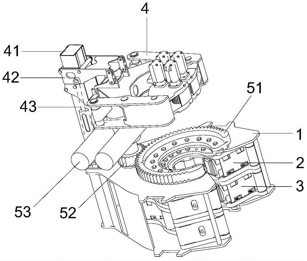
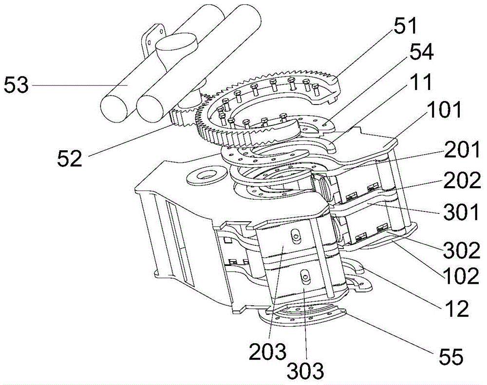
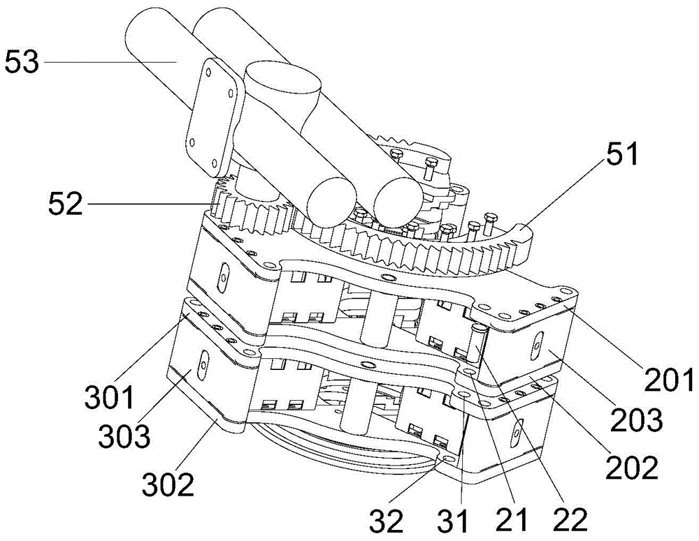
[0034] Figure 1-Figure 4 Shown is the structural representation of the iron driller's pliers body of the embodiment of the present invention, wherein figure 1 It is a structural schematic diagram of an iron driller's pliers body of the present invention; figure 2 It is an exploded schematic diagram of the side structure of the punching pliers and the clamping pliers of the present invention; image 3 is the invention figure 2 Schematic diagram of the rear structure without the rack; Figure 4 It is an exploded schematic view o...


PUM


Abstract

The invention discloses an iron roughneck clamp body. The iron roughneck clamp body comprises a rack, punching pliers, and a clamping clamp, the clamping pliers and the clamping clamp are arranged in the rack, a cover plate of the clamping pliers is provided with a gear ring along the circumferential direction of a clamp opening, the gear ring is engaged with a gear, and the gear is connected with a driving device. According to the iron roughneck clamp body, the punching torque is provided by the adoption of a transmission method of the gear and the gear ring, the punching of a pipe column is realized, compared with the method of applying the punching torque by the adoption of a punching oil cylinder in the prior art, the upper shacking angle is large, and the upper shackling efficiency is higher. The invention further discloses an iron roughneck and petroleum drilling and production equipment.

Description

technical field [0001] The invention relates to the field of petroleum equipment, in particular to an iron driller's pliers, iron drillers and oil drilling equipment using the pliers. Background technique [0002] In oil drilling and workover operations, the connection and disassembly of pipe strings such as drill pipes and drill collars is a repetitive and heavy work. The current common solution is to configure hydraulic tongs or power tongs in oil drilling equipment. In this operation mode, hydraulic tongs or power tongs are frequently moved between the wellhead, retractable position, rat hole, and column storage position. It still needs to be completed manually, so that the labor intensity and safety risk are still relatively large. Therefore, it is gradually replaced by iron drillers at present. [0003] The Iron Driller is a safe and efficient equipment for making and breaking out drilling tools. It mainly includes a jib device and a pliers body. The movement of the ...

Claims


Application Information

Patent Timeline
IPC IPC(8): E21B19/16
Inventor 程建民赵勇刘存勇
Owner HUNAN SANY PETROLEUM TECH
Learn More