
A hybrid high-pressure jet nozzle

A high-pressure jet, hybrid technology, used in mechanically driven excavators/dredgers, etc., can solve the problems of poor uniformity of flow velocity and direction distribution, limited traction, small jet energy and impact force, etc. Uniform directional distribution, reduced purchase and installation costs, effects of large jet energy and impact force

Inactive Publication Date: 2017-06-13
WUHAN UNIV OF TECH
View PDF9 Cites 0 Cited by
  • Summary
  • Abstract
  • Description
  • Claims
  • Application Information

AI Technical Summary

Problems solved by technology

The nozzle has strong jet energy and impact force, and good erosion resistance, but it also has the defect of small jet area; patent CN203822274U discloses a self-excited and other-excited pulse jet nozzle, which is a cylindrical nozzle body. The inner cavity of the cylindrical nozzle body sequentially forms a nozzle water inlet hole, a self-excited oscillation cavity, and a lower nozzle hole, and the self-excited oscillation cavity is provided with other excitation holes connected to the outside of the cylindrical nozzle body
The jet energy and impact force of the nozzle are strong, but the uniformity of the flow velocity and direction distribution is poor, and the jet area is small; the patent CN203081296U discloses a hydraulic jet multi-nozzle radial drilling device, which solves the problem of the prior art The limited traction force of the front-end jet nozzle leads to the problem of short horizontal length of radial drilling and small drilling diameter. It has strong jet energy and impact force, but the jet area is small
[0004] The above-mentioned high-pressure jet nozzles have small jet areas or small jet energy and impact force, and cannot meet the requirements of large jet area and strong jet impact force at the same time.
For non-high-pressure jet nozzles, especially fan-shaped nozzles, due to their special nozzle shape, they will produce flat and uniform flat jets. It will produce a large jet area, but its jet energy and impact force are small, and it is necessary to use a pump set with increased pressure when it is used alone in a dredger, which undoubtedly increases the technical difficulty and cost.

Method used


Image

  • A hybrid high-pressure jet nozzle
  • A hybrid high-pressure jet nozzle
  • A hybrid high-pressure jet nozzle

Examples


Embodiment Construction

[0023] The present invention will be described in detail below in conjunction with the accompanying drawings and embodiments.

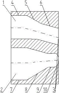
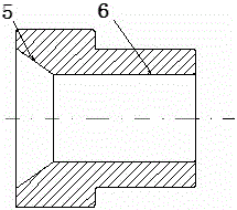
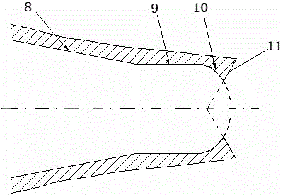
[0024] Such as figure 1 As shown, a hybrid high-pressure jet nozzle includes a nozzle body. Inside the nozzle body, there are mutually independent conical straight flow channels 1 and fan-shaped flow channels 2. The conical straight flow channels 1 include sequentially connected first transition Hole 4, the first conical liquid inlet hole 5 and cylindrical spray hole 6, such as figure 2 As shown, the first conical liquid inlet hole 5 and the cylindrical liquid injection hole 6 are coaxial; the fan-shaped flow channel 2 includes a second transition hole 7, a second conical liquid inlet hole 8, a cylindrical inlet Liquid hole 9 and oval spray hole 10, such as image 3 As shown, the second tapered liquid inlet hole 8, the cylindrical liquid inlet hole 9 and the oval spray hole 10 are concentric; the first transition hole 4 and the second transition ho...


PUM


Abstract

The invention relates to a mixing high-pressure jet nozzle. The mixing high-pressure jet nozzle is characterized in that the interior of a nozzle body is provided with a straight-taper flow channel and a fan-shaped flow channel, both of which are independent; the straight-taper flow channel comprises a first transition hole, a first tapered liquid inlet hole and a cylindrical liquid-spraying hole; the first transition hole, the first tapered liquid inlet hole and the cylindrical liquid-spraying hole are connected in sequence; the first tapered liquid inlet hole and the cylindrical liquid-spraying hole are arranged concentrically; the fan-shaped flow channel comprises a second transition hole, a second tapered liquid inlet hole, a cylindrical liquid inlet hole and an elliptical liquid-spraying hole; the second transition hole, the second tapered liquid inlet hole, the cylindrical liquid inlet hole and the elliptical liquid-spraying hole are connected in sequence; the second tapered liquid inlet hole, the cylindrical liquid inlet hole and the elliptical liquid-spraying hole are arranged concentrically; a liquid inlet is combined by a first transition hole and a second transition hole; a mixing outlet is combined by the cylindrical liquid-spraying hole and the elliptical liquid-spraying hole; the first tapered liquid inlet hole, the second tapered liquid inlet hole and the elliptical liquid-spraying hole are wide at the front portion and narrow at the back portion along the liquid-flowing direction; and axes of the cylindrical liquid-spraying hole and of the elliptical liquid-spraying hole are intersected with the included angle being an acute angle. The mixing high-pressure jet nozzle has a large jet area and great jet impact force.

Description

technical field [0001] The invention relates to a hybrid high-pressure jet nozzle, which is mainly used in sucker dredgers and trailing suction dredgers to provide high-pressure jets. Background technique [0002] Dredging engineering is widely used in islands, reefs, rivers, lakes, reservoirs, ports, waterways and other waters with a large amount of sediment. Dredging engineering is to excavate underwater sediments. By dredging, the water depth and The width meets the predetermined requirements. At present, the construction machinery used for underwater dredging at home and abroad is mainly the dredger. The trailing suction dredger is a ship type that is widely used at present. The existing trailing suction dredger generally uses high-pressure water jets to assist the drag head to dig. , To increase the excavation depth and mud concentration, and reduce the excavation resistance, the suction cup dredger is another dredger that uses high-pressure jet technology as the minin...

Claims


Application Information

Patent Timeline
Patent Type & Authority Patents(China)
IPC IPC(8): E02F3/92
Inventor 朱汉华张培建张喜胜李鹏举王瑞陈志坚司伟刘永杰任海强马子超
Owner WUHAN UNIV OF TECH
Learn More