Ball-milling device for materials

A ball mill and material technology, applied in the direction of grain processing, etc., can solve the problems of increased wear of the liner, increased wear of the liner and ball, and high electrical power consumption of the ball mill. Effect

Inactive Publication Date: 2015-09-09
江苏博拓新型建筑材料股份有限公司
View PDF0 Cites 8 Cited by
  • Summary
  • Abstract
  • Description
  • Claims
  • Application Information

AI Technical Summary

Problems solved by technology

The sphere is generally made of metal or non-metallic materials, and rotates with the cylinder of the ball mill. The grinding body rotates, throws, rolls, slides, etc. in the cylinder, and the grinding body and the material form a transfer of energy through impact and friction. , crushing materials by crushing and grinding, but because of the smooth surface of the existing grinding body, most of the energy is not utilized in the process of impact and friction, while the heat energy and sound energy are lost, and the effective utilization rate of energy is very low. Low, only 1 to 3%, the ball mill has high power consumption, and the barrel of the ball mill is also easily damaged. In some cases, a simple wear-resistant liner is added to the barrel to prolong the service life of the barrel
Whether the wear-resistant liner has a completely smooth surface or some patterns are cast on the surface, its lifting effect on the grinding body basically depends on the static friction between the liner and the grinding body. The static friction coefficient of the wet ball mill is 0.35, and the static friction coefficient of the dry ball mill is 0.4. Since the static friction coefficient is much smaller than the actual need, it is inevitable that the grinding body will slide, which will reduce the lifting height of the liner and increase the wear of the liner and the ball. Reduce the grinding efficiency of the ball mill and increase the wear of the liner
[0003] In addition, in the existing ball mill, materials with large particles, medium particles and small particles are mixed together and ground by a kind of steel ball, which not only takes a long time, but also the effect of ball milling is not very good

Method used


Image

  • Ball-milling device for materials
  • Ball-milling device for materials
  • Ball-milling device for materials

Examples


Embodiment Construction

[0014] The present invention will be further explained below in conjunction with the accompanying drawings and specific embodiments. It should be understood that the following specific embodiments are only used to illustrate the present invention and are not intended to limit the scope of the present invention. It should be noted that the words "front", "rear", "left", "right", "upper" and "lower" used in the following description refer to the directions in the drawings, and the words "inner" and "outer ” refer to directions towards or away from the geometric center of a particular part, respectively.

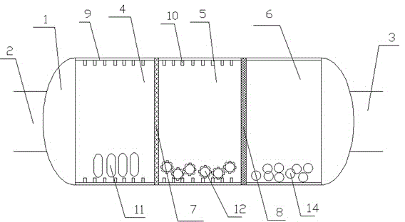
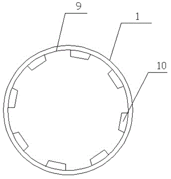
[0015] As shown in the figure, a material ball milling device includes a cylinder body 1, a material inlet 2 and a material outlet 3 are provided at both ends of the cylinder body 1, a first partition 7 and a second partition 8 are arranged inside the cylinder 1, and the second partition A dividing plate 7 and the second dividing plate 8 are all provided with filter holes, the ...


PUM


Abstract

The invention discloses a ball-milling device for materials. The ball-milling device comprises a barrel. A material inlet and a material outlet are formed in two ends of the barrel, a first partition plate and a second partition plate are arranged inside the barrel, filter holes are formed in the first partition plate and the second partition plate, the diameters of the filter holes in the first partition plate are larger than those of the filter holes in the second partition plate, the barrel is divided into a first barrel, a second barrel and a third barrel by the first partition plate and the second partition plate, abrasion-resistant lining plates are arranged on the inner walls of the first barrel, the second barrel and the third barrel, protrusions are arranged on the lining plates of the first barrel and the second barrel, grinding steel balls are respectively arranged in the first barrel, the second barrel and the third barrel, cylindrical steel ball bodies are arranged in the first barrel, arc-shaped ends are respectively connected to the upper ends and the bottoms of the cylindrical steel ball bodies, and a plurality of protrusions are arranged on the surfaces of the steel balls in the second barrel. The ball-milling device has the advantages that excellent ball-milling effects can be realized by the ball-milling device, the ball-milling device is short in ball-milling time, and the service lives of the lining plates can be prolonged.

Description

technical field [0001] The invention relates to a building material crushing equipment, in particular to a material ball milling device. Background technique [0002] The ball mill is the key equipment for crushing the material after it is crushed. It is widely used in non-ferrous metal beneficiation and other production industries. The existing ball mill generally uses the centrifugal force during rotation to lift the internal steel ball, and through the interaction between the steel ball and the material The material is crushed. The sphere is generally made of metal or non-metallic materials, and rotates with the cylinder of the ball mill. The grinding body rotates, throws, rolls, slides, etc. in the cylinder, and the grinding body and the material form a transfer of energy through impact and friction. , crushing materials by crushing and grinding, but because of the smooth surface of the existing grinding body, most of the energy is not utilized in the process of imp...

Claims


Application Information

Patent Timeline
Patent Type & Authority Applications(China)
IPC IPC(8): B02C17/06B02C17/10B02C17/18B02C17/22
CPCB02C17/06B02C17/10B02C17/20B02C17/22
Inventor 罗乃将孔加春
Owner 江苏博拓新型建筑材料股份有限公司
Why Eureka
Try Eureka