
Control system for drainage of minimally-invasive operation in aesthetic and plastic surgery

A technique of minimally invasive surgery and plastic surgery, applied in the direction of wound drainage, etc., can solve problems such as insufficient drainage, damage to fragile tissues such as nerves, and affecting patients' activities and rest

Inactive Publication Date: 2015-09-09
王琪影
View PDF4 Cites 4 Cited by
  • Summary
  • Abstract
  • Description
  • Claims
  • Application Information

AI Technical Summary

Problems solved by technology

[0005] The purpose of the present invention is to provide a control system for minimally invasive surgical drainage in cosmetic and plastic surgery, aiming to solve the problem of insufficient drainage of rubber strips in existing minimally invasive surgical drainage of cosmetic and plastic surgery, which is easy to form hematoma; The diameter of the silicone rubber drainage tube in the side hole is relatively thick, which can lead to poor incision healing and obvious scars. The drainage bag or drainage device connected to it is inconvenient to fix and carry, which affects the patient's activities and rest; the traditional negative pressure drainage device can control the pressure. And the monitoring of drainage volume is not accurate, which may cause damage to surrounding tissues, especially fragile tissues such as nerves

Method used


Image

  • Control system for drainage of minimally-invasive operation in aesthetic and plastic surgery
  • Control system for drainage of minimally-invasive operation in aesthetic and plastic surgery
  • Control system for drainage of minimally-invasive operation in aesthetic and plastic surgery

Examples


Embodiment Construction

[0018] In order to make the objectives, technical solutions and advantages of the present invention clearer, the present invention will be further described in detail below in conjunction with embodiments. It should be understood that the specific embodiments described herein are only used to explain the present invention, but not to limit the present invention.

[0019] The application principle of the present invention will be further described below with reference to the drawings and specific embodiments.

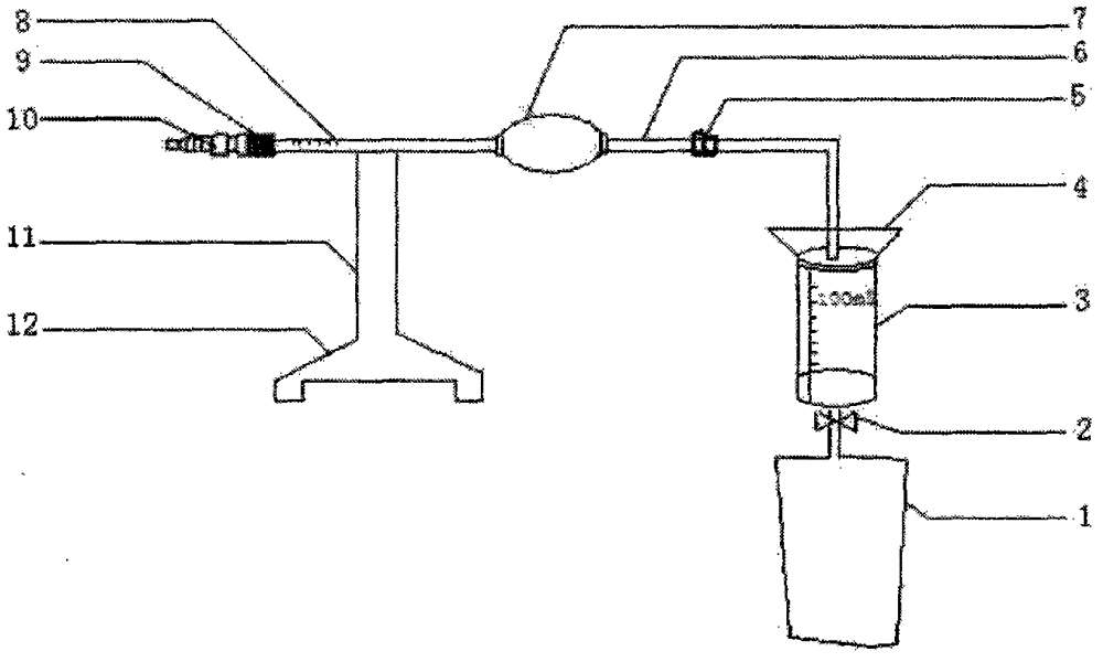
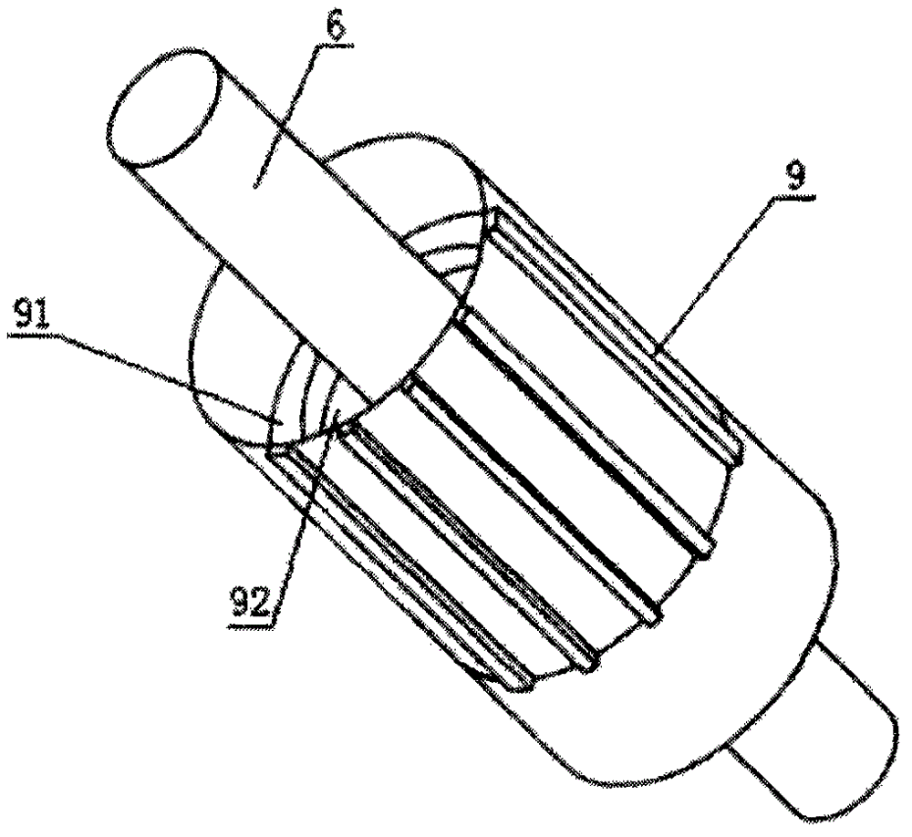
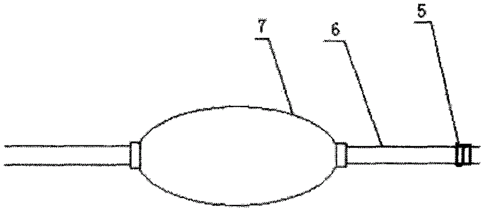
[0020] See Figure 1 ~ Figure 3 In the embodiment of the present invention, a minimally invasive drainage control system for cosmetic plastic surgery includes a liquid storage bag 1, a measuring cylinder 3, a drainage tube 6, an air bag 7, a connector 9, a connector 10, and a bracket 11. The liquid storage bag 1 is PVC material, the tube at the upper end of the liquid storage bag 1 is equipped with a control valve 2. The control valve 2 is made of medical hard plastic materi...


PUM


Abstract

The invention discloses a control system for drainage of a minimally-invasive operation in the aesthetic and plastic surgery. The control system comprises a liquid storage bag, a measuring cylinder, a drainage pipe, an air bag, a connecting device, a connector and a support; a silica gel drainage pipe is arranged on the drainage pipe, a bayonet socket connected with an injection syringe is arranged at the back end of the drainage pipe, and at least two drainage holes are formed in a pipe wall of the front end of the drainage pipe; a plug matching a connecting hole of the bayonet socket is arranged, a connecting belt is arranged on the plug, and the other end of the connecting belt is connected with the bayonet socket; and length metering scales are arranged on the pipe wall of the front end of the drainage pipe. By means of the control system, blood clots, purulent blood and the like in hydrops of the human body can be effectively drained, the unstable drainage process caused by shaking is avoided, the numerical value of the drained hydrops is accurately recoded, and the medical negligence of errhysis and hydrops outflow can be avoided; after suction is carried out, the connecting hole in the bayonet socket is plugged through the plug, so that wound infections are prevented, and only the plug needs to be opened when suction is carried out next time; and the control system has the beneficial effects of being simple in structure, convenient to operate, safe in use, good in treatment effect and the like.

Description

Technical field [0001] The invention belongs to the technical field of cosmetic plastic surgery, and in particular relates to a drainage control system for minimally invasive surgery in cosmetic plastic surgery. Background technique [0002] Surgical drainage is an important clinical diagnosis and treatment technique. The concept of surgical drainage was formed in the 15th century BC. At that time, medical scientists observed that the patient’s overall condition improved after the infected wound or abscess spontaneously ruptured. As a result, they realized that the application of mechanical drainage may improve the condition and promote heal. With the development of science and technology, medical clinical imaging intervention, guided percutaneous drainage, endoscopic drainage, etc. have enriched the content of traditional surgical drainage. Drainage is divided into diagnostic drainage and therapeutic drainage, which can help stop bleeding and prevent hematoma formation in plas...

Claims


Application Information

Patent Timeline
IPC IPC(8): A61M27/00
Inventor 王琪影
Owner 王琪影
Learn More