Aerial cleaning robot and cleaning method
A technology for cleaning robots and cleaning mechanisms, which is applied to machine parts, cleaning machinery, carpet cleaning, etc., and can solve problems such as failure to achieve cleaning, existence of high-rise walls/glass surfaces, and waste of electricity.
- Summary
- Abstract
- Description
- Claims
- Application Information
AI Technical Summary
Problems solved by technology
Method used
Image
Examples
Embodiment 1
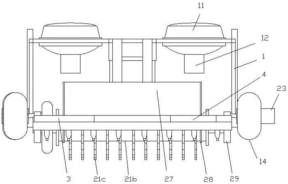
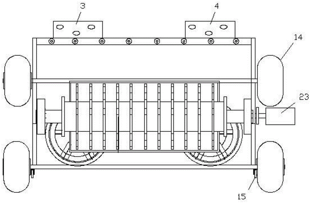
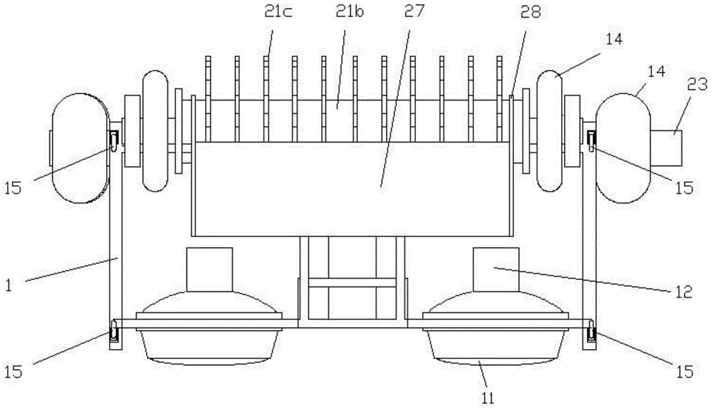
[0033] Embodiment one, see appendix Figure 1 to Figure 8 A high-altitude cleaning robot shown is used to clean high-rise walls / glass surfaces, and includes a propulsion balance frame 1 and a cleaning mechanism 2. The cleaning mechanism 2 is arranged on the propulsion balance frame 1. The cleaning mechanism 2 includes a roller brush 21, a shaft 22 and The roller brush motor 23 that is connected with the roller brush 21 through the shaft 22 and controls the roller brush 21 to rotate, is provided with at least one thrust fan 11 on the propulsion balance frame 1, specifically, the length of the propulsion balance frame 1 is less than 4 meters, and the thrust fan 11 1-3 are provided; the length of the propulsion balance frame 1 is 4-8 meters, and 4-6 thrust fans 11 are provided. The length of propelling balance frame 1 can be selected in 1-8 meter, as when propelling balance frame 1 meter, 1 or 3 thrust fans 11 can be set on this propelling balance frame 1, when the length of prop...
Embodiment 2
[0044] Embodiment two, such as Figure 9-11 As shown, the difference from Example 1 is that each bristle is trapezoidal and flat, the end of each bristle has a smaller contact surface with the stain, and the greater the pressure, it can be used for some areas that are relatively small but Stains with relatively strong adhesion; the side of the propelling balance frame 1 close to the high-rise wall / glass surface is a convex surface 13b, which is suitable for U-shaped wall surfaces of high-rise walls / glass surfaces. The shaft 22 is a second shaft 22b, the roller 21a is provided with an axial through hole 26, the second shaft 22b passes through the axial through hole 26, the two ends of the second shaft 22b pass through the roller 21a, the second shaft 22b At least one pneumatic rubber wheel 14 is provided on each end or / and on both sides of the side close to the high-rise wall / glass surface, and the two side baffles 28 correspond to the two ends of the second shaft 22b one by on...
Embodiment 3
[0045] Embodiment three, such as Figure 12-15 As shown, different from Embodiment 1, the wide sides W where a plurality of flat bristles 21c are in contact with the roller sleeve 21b are arranged along the circumferential direction S2 of the roller sleeve 21b, and each flat bristle 21c can face the wall with The narrow side n of the bristles 21c cleans, that is, cleans along the thickness of the bristles 21c, which can clean some relatively small areas, such as walls with multiple vertical gaps, because each flat bristle 21c can clean the walls with bristles. 21c narrow side n for cleaning, then its pressure is higher, and it can remove stains with greater adhesion. Although the bristles 21c in this embodiment are the same as the first embodiment, they are strip-shaped and flat, but the effects are different. Because they are in the shape of a strip, the two ends of the end faces of each bristle 21c that are in contact with the stains have a right angle respectively, and the ...
PUM
 Abstract
Description
Claims
Application Information
 - R&D Engineer
- R&D Manager
- IP Professional
- Industry Leading Data Capabilities
- Powerful AI technology
- Patent DNA Extraction
Browse by: Latest US Patents, China's latest patents, Technical Efficacy Thesaurus, Application Domain, Technology Topic, Popular Technical Reports.
© 2024 PatSnap. All rights reserved.Legal|Privacy policy|Modern Slavery Act Transparency Statement|Sitemap|About US| Contact US: help@patsnap.com


