Perforated drum of an axial turbine-engine compressor

A technology for turbine engines, compressors, applied in the direction of engine functions, engine components, components of pumping devices for elastic fluids, etc., can solve problems such as unsatisfactory solutions, achieve small damage, and reduce the risk of clogging , the effect of simple geometric structures

Active Publication Date: 2017-01-11
SAFRAN AERO BOOSTERS SA
View PDF15 Cites 4 Cited by
  • Summary
  • Abstract
  • Description
  • Claims
  • Application Information

AI Technical Summary

Problems solved by technology

The blades of low pressure compressors are usually delicate and therefore this solution is not satisfactory
In addition, this configuration creates additional costs for housing the cavities

Method used


Image

  • Perforated drum of an axial turbine-engine compressor
  • Perforated drum of an axial turbine-engine compressor
  • Perforated drum of an axial turbine-engine compressor

Examples


Embodiment Construction

[0053] In the following description, the terms inner or inner and outer or outer relate to a position relative to the axis of rotation of the axial turbine engine. The axial direction corresponds to a direction along the axis of rotation of the turbine engine. Upstream and downstream are referred to with reference to the main flow direction of the flow in the turbine engine.

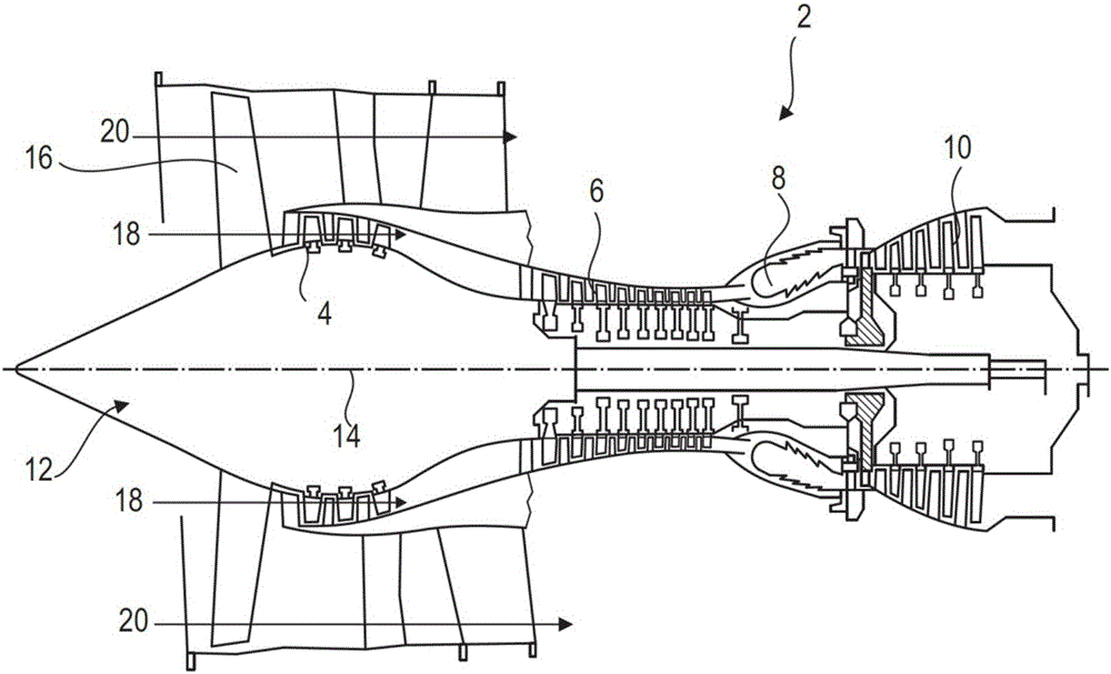
[0054] figure 1 An axial turbine engine is shown in a simplified manner. In this precise case, it's the ducted fan turbine engine used to power the aircraft. The turbojet engine 2 comprises a first compression stage called a low-pressure compressor 4 , a second compression stage called a high-pressure compressor 6 , a combustion chamber 8 and a one- or multi-stage turbine 10 . In operation, the mechanical power of the turbine 10 , transmitted via the central shaft to the rotor 12 , moves the two compressors 4 and 6 . The latter includes rows of rotor blades associated with rows of stator blades. The...


PUM


Abstract

A rotor, in particular, a drum of a low-pressure compressor of a turbojet aero engine has an outer annular wall delimiting a primary annular flow of the turbine engine, sealing devices with two rubbing strips or annular ribs formed on the wall. The rubbing strips cooperate by abrasion with inner shrouds. In addition, the annular wall includes rows of intake orifices for leakages which are arranged between each pair of rubbing strips in order to aspirate the recirculation leakages there. A collector for leakages is formed inside the rotor by means of a composite web, then evacuates the parasitic flow downstream of the turbine engine via the central shaft.

Description

technical field [0001] The present invention relates to cycle leakage of bladed rotors of axial flow turbine engines. The invention also relates to a compressor of an axial turbine engine. The invention also proposes an axial turbine engine such as a turbojet aeroengine. Background technique [0002] Compressors, such as turbojet aeroengines, have a series of rows of blades. Some of these rows are associated to the stator and others to the rotor. The definition of the blade profile allows the process of annular flow to recover energy by causing the flow to be compressed or expanded. Depending on the management of parasitic discharges, the efficiency of these mechanisms acts on the flow. [0003] In fact, when the turbine engine is running, the leakage flow passes around the rows of stator blades. They circulate between the rotor and the inner shroud. These circulating flows cause losses through mixing. This manifests itself as a reduction in the flow being effectively...

Claims


Application Information

Patent Timeline
Patent Type & Authority Applications(China)
IPC IPC(8): F04D29/32F04D29/54F04D29/66
CPCF04D29/324F04D29/542F04D29/662F01D5/06F01D11/001F01D11/04F02C6/08F05D2260/6022F04D29/164Y02T50/60F04D27/009F04D29/083F04D29/321F04D29/522F04D29/682
Inventor S.希尔诺克斯
Owner SAFRAN AERO BOOSTERS SA
Why Eureka
Try Eureka