
Motor stator and winding method thereof

A winding method and motor technology, applied in the shape/style/structure of winding conductors, magnetic circuit shape/style/structure, magnetic circuit static parts, etc., can solve the problem of large consumables, narrow installation location, and enlarged motor volume and other problems, to achieve the effect of high output power, easy installation and compact structure

Active Publication Date: 2015-09-02
QUANZHOU KPL ELECTRIC APPLIANCE FOR VEHICLE
View PDF8 Cites 13 Cited by
  • Summary
  • Abstract
  • Description
  • Claims
  • Application Information

AI Technical Summary

Problems solved by technology

[0002] With the rapid development of automotive technology, especially electric vehicle technology, the power requirements for automotive motors are also increasing, and the increase in power will inevitably lead to an increase in the volume of the motor; There are many, and the installation location provided for the motor is becoming narrower and more crowded. In the limited space, the power of the existing motor can no longer meet the demand. Therefore, the contradiction between the volume and power of the motor has become a technology for high-power research and development of the motor. problem
[0003] The stator windings of existing electric motors generally use round copper wires to form coil groups for winding. Since the cross-sectional area of ​​round copper wires is relatively small, each coil group needs to contain more round copper wires, and the volume of the formed coil group Relatively large, the heat dissipation effect is poor, and there are many consumables, and the cost is high; in addition, in the existing stator windings, the coil groups of the same phase are generally wound separately and then connected in parallel, and then The phases are connected to each other in a star or delta connection, so that when the power of the motor increases, its volume will become larger and larger, and the number of round copper wires that need to be used is also large, and the cost is relatively high

Method used


Image

  • Motor stator and winding method thereof
  • Motor stator and winding method thereof
  • Motor stator and winding method thereof

Examples


Embodiment 1

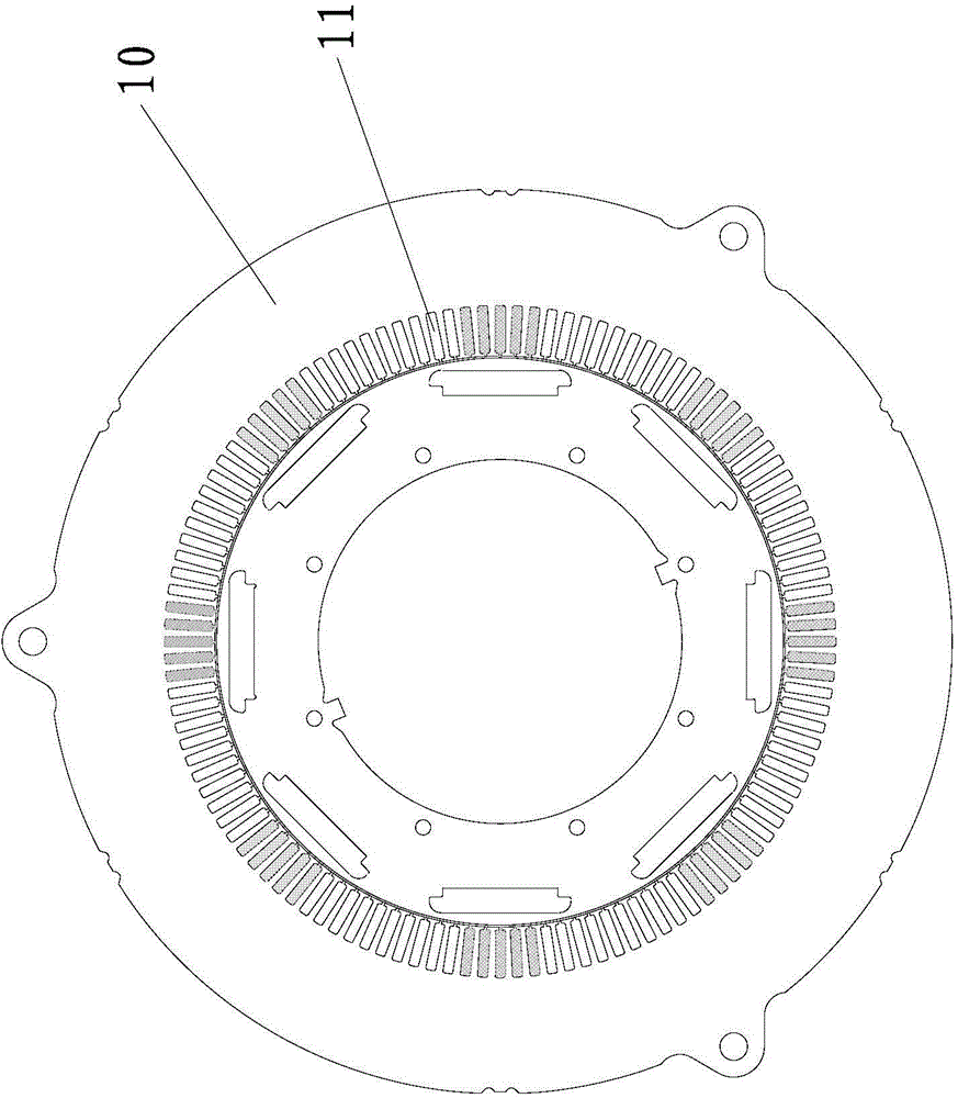
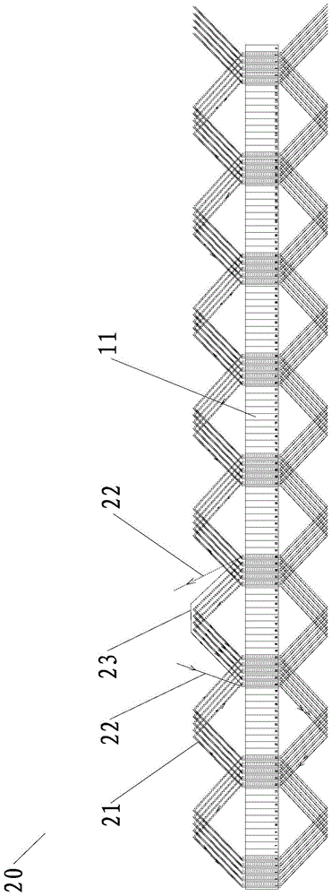
[0039] The motor stator provided by this embodiment, such as Figure 1-2 As shown, it includes an iron core 10 and a stator winding 20 wound on the iron core 10 .

[0040] Such as figure 1 As shown, the iron core 10 is equidistantly provided with stator slots 11 of 120 slots, and the shape of the stator slots 11 can be a conventional shape, such as a rectangular slot, and the slot walls of the stator slots 11 of each slot are laid with Matching insulating paper (not shown in the figure), the insulating paper is also the insulating paper used in the conventional motor stator, and will not be described in detail here.

[0041]The stator winding 20 is a three-phase winding matched with the iron core 10, and the number of magnetic pole pairs is four. Each phase of the stator winding 20 includes two groups of stator coil groups wound on the corresponding stator slots 11 on the iron core 10 by means of wave winding, and the two groups of stator coil groups are respectively wound o...

Embodiment 2

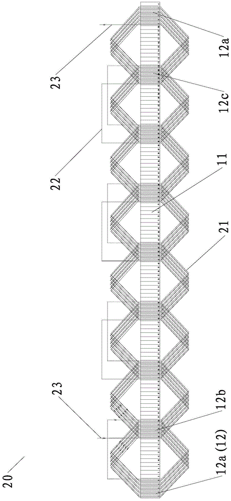
[0049] The difference between this embodiment and the first embodiment is that the stator winding 20 of this embodiment is different from that of the first embodiment. In this embodiment, the stator winding is also a three-phase winding, the number of magnetic pole pairs is four, and the winding method of each phase is the same. Each phase of the stator winding 20 includes eight sets of stator coil groups wound in a stacked manner. Each set of stator coil sets is respectively stacked on two sets of stator slot sets separated by ten slots. Each set of stator slot sets includes five slot phases. Adjacent stator slots, the winding direction of each set of stator coil groups is the same, and two adjacent sets of stator coil sets share a set of stator slot sets, except for two sets of adjacent stator coil sets, the adjacent two sets of stator coil sets The coils are connected in series through a group of connecting coils. The two ends of the stator coil group after series connectio...

Embodiment 3

[0057] The difference between this embodiment and Embodiment 2 is that, in this embodiment, the number of stator slots 11 on the iron core 10 is 126 slots, the number of magnetic pole pairs is three, and each phase of the stator winding 20 includes six groups that are wound in a stacked manner. The set stator coil group 21, each group of stator coil groups are stacked on two sets of stator slot groups with fourteen slots at intervals, each group of stator slot groups includes seven adjacent stator slots 11, each group of stator coil groups 21 The winding direction is the same, and the adjacent two sets of stator coil groups 21 share a set of stator slot groups, except for the two adjacent stator coil groups 21, the adjacent two sets of stator coil groups are respectively connected through a set of coils Groups are concatenated end to end.

[0058] The winding method of the stator winding 20 of this implementation is as follows: image 3 As shown, each corresponding electronic...


PUM


Abstract

The invention provides a motor stator and a winding method thereof. The motor stator comprises an iron core and a stator winding. Stator slots are formed in the iron core at equal intervals. Each phase of the stator winding contains a stator coil group based on winding in a wave winding mode or lap winding mode and a connecting coil group enabling two of more than two groups of stator coil groups to be connected in series; and two winding leading-out wire groups are formed naturally at the two ends of the stator coil groups after series connection. Each stator coil group, each connecting coil group, and each winding leading-out wire group contains four flat type copper wires respectively. In addition, the invention also provides a winding method of the motor stator. On the basis of the wave winding or lap winding way, the corresponding stator windings of all phases are wound and the stator coil groups of all phases of the stator winding are connected in series. Under the circumstances that the motor stator volume is not changed, the motor power is substantially improved; and the power is high and the size is small relatively.

Description

technical field [0001] The invention relates to an internal part of a motor and a manufacturing method thereof, in particular to a motor stator with relatively large power and relatively small volume and a winding method thereof. Background technique [0002] With the rapid development of automotive technology, especially electric vehicle technology, the power requirements for automotive motors are also increasing, and the increase in power will inevitably lead to an increase in the volume of the motor; There are many, and the installation location provided for the motor is becoming narrower and more crowded. In the limited space, the power of the existing motor can no longer meet the demand. Therefore, the contradiction between the volume and power of the motor has become a technology for high-power research and development of the motor. problem. [0003] The stator windings of existing motors generally use round copper wires to form coil groups for winding. Since the cros...

Claims


Application Information

Patent Timeline
Patent Type & Authority Applications(China)
IPC IPC(8): H02K1/12H02K1/16H02K3/28H02K3/04H02K3/12
Inventor 陈孙艺
Owner QUANZHOU KPL ELECTRIC APPLIANCE FOR VEHICLE
Learn More