
Identification circuit for USB Type-C interface

A technology for identifying circuits and interfaces, applied in the field of interface identification, it can solve the problems of different identification circuits and different performances, and achieve the effect of precise control and small temperature influence.

Active Publication Date: 2015-09-02
SALCOMP SHENZHEN CO LTD
View PDF2 Cites 31 Cited by
  • Summary
  • Abstract
  • Description
  • Claims
  • Application Information

AI Technical Summary

Problems solved by technology

The identification circuits of the existing USB Type-C interface are different, and the performance is different, which needs to be further improved and perfected

Method used


Image

  • Identification circuit for USB Type-C interface
  • Identification circuit for USB Type-C interface
  • Identification circuit for USB Type-C interface

Examples


specific Embodiment approach 1

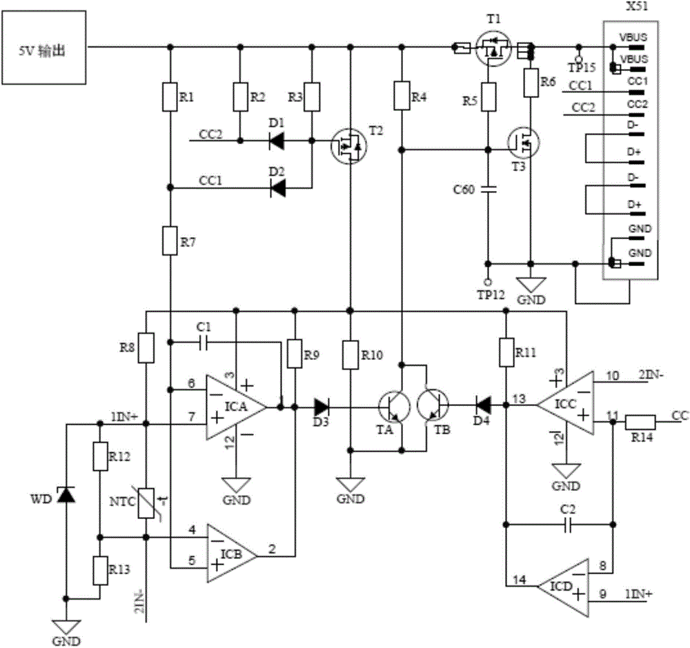
[0025] a kind of like Attached The identification circuit of the USB Type-C interface shown in the figure, one end is connected to the 5V output end of the USB Type C adapter, and the other end is connected to the USB Type C terminal equipment, and the first input terminal CC1 of the terminal equipment passes through the 3A (marked Nominal value) The first pull-up resistor R1 is connected to the 5V output terminal of the USB Type C adapter, and the second input terminal CC2 of the terminal device is connected to the USB Type C adapter through the 3A (nominal value) second pull-up resistor R2 with isolation effect Connected to the 5V output terminal of the terminal equipment, the first input terminal CC1 of the terminal equipment, and the second input terminal CC2 of the terminal equipment have different functions in different applications. The transmitted signals include communication signals and voltage signals. The first pull-up resistor R1 and the second The pull-up resist...

specific Embodiment approach 2

[0049] An identification circuit of a USB Type-C interface is basically the same as the specific embodiment one, the difference is that:

[0050] The third electronic switch is a P-type switching triode, which does not need to be connected with a voltage stabilizing resistor.

specific Embodiment approach 3

[0051] An identification circuit of a USB Type-C interface is basically the same as the specific embodiment one, the difference is that:

[0052] The discharge branch used to provide the output terminal VBUS when the terminal device is removed is connected between the output terminal VBUS and GND of the charger. Shan Housheng (Uniohm) Electronics Industry Co., Ltd. produced a 1KΩ discharge resistor.


PUM


Abstract

The invention discloses an identification circuit for a USB Type-C interface. One end of the identification circuit is connected with a 5V output end of an adapter, and the other end is connected with terminal equipment. The identification circuit is characterized by comprising a first field-effect transistor serving as an isolating switch, a first current-limiting resistor connected to the gate of the first field-effect transistor as well as an electronic switch for controlling connection or disconnection of the first field-effect transistor, wherein the electronic switch comprises double-base switching triode and a second current-limiting resistor connected between a collector of the double-base switching triode and an output end of a charger, and the double-base switching triode comprises a first switching triode and a second switching triode; the identification circuit further comprises a first electronic switch and a second electronic switch which are used for controlling connection or disconnection of the first switching triode and the second switching triode and have a delay function. The identification circuit performs control accurately, is hardly influenced by temperature, meets the requirement of the USB Type-C standard, and can perform identification within 100-200 ms of the standard limited time according to communication signals given by the terminal equipment so as to determine whether power is supplied to the terminal equipment.

Description

technical field [0001] The invention relates to interface identification, in particular to an identification circuit of a USB Type-C interface. Background technique [0002] Universal Serial Bus, also known as Universal Serial Bus (abbreviated as USB) Type-C interface, is a new USB interface form, which is accompanied by the latest USB3.1 standard in Intel Developer Forum 2014 (IDF14) It was officially released to the public at the exhibition. It integrates data transmission, video output and charging, with a maximum data transmission speed of 10Gbps, which is close to High Definition Multimedia Interface (HDMI) 1.4 (10.2Gbps), and can directly transmit 4K / 30p video files, and supports High-bandwidth Digital Content Protection (High-bandwidth Digital Content Protection, the abbreviation is HDCP), the size of the socket end is as small as the original Micro USB specification, about 8.3mm×2.5mm, USB Type The -C data cable can pass 5A current, and also supports "USB Power Del...

Claims


Application Information

Patent Timeline
Patent Type & Authority Applications(China)
IPC IPC(8): G06F13/42
CPCG06F13/4282
Inventor 吴茂东王腾月朱卡
Owner SALCOMP SHENZHEN CO LTD
Learn More