
Embedded touch display screen, driving method thereof and display device

A touch display, embedded technology, used in static indicators, instruments, electrical digital data processing and other directions, can solve the problems of high production cost, low light transmittance, and module thickness.

Active Publication Date: 2015-09-02
BOE TECH GRP CO LTD +1
View PDF2 Cites 26 Cited by
  • Summary
  • Abstract
  • Description
  • Claims
  • Application Information

AI Technical Summary

Problems solved by technology

Among them, the plug-in touch screen is produced separately from the touch screen and the display screen, and then bonded together to form a display screen with touch function. The plug-in touch screen has disadvantages such as high production cost, low light transmittance, and thick modules.

Method used


Image

  • Embedded touch display screen, driving method thereof and display device
  • Embedded touch display screen, driving method thereof and display device
  • Embedded touch display screen, driving method thereof and display device

Examples


Embodiment 1

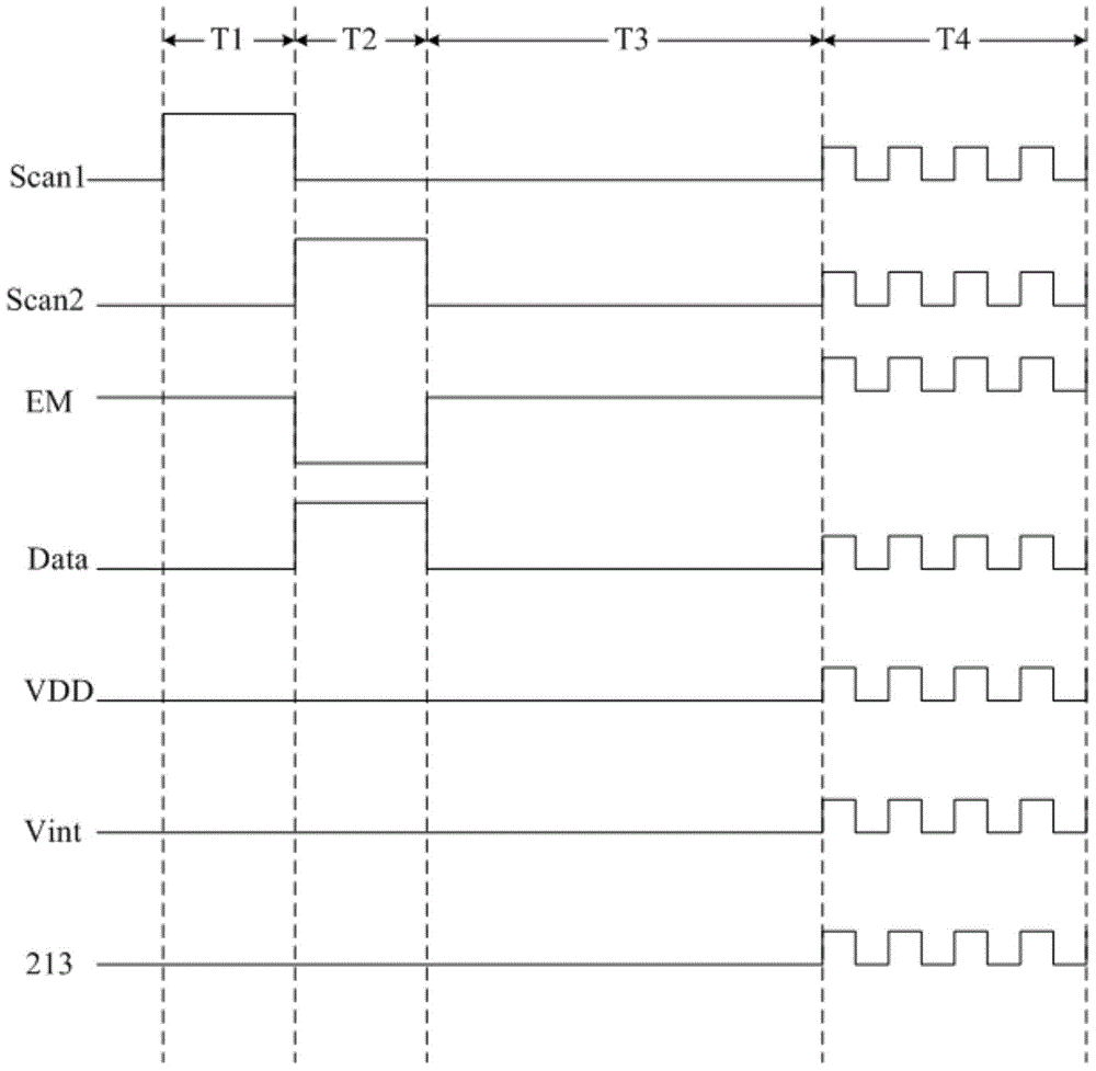
[0096] In the first phase T1 (reset charging phase), Scan1=1, Scan2=0, EM=1.

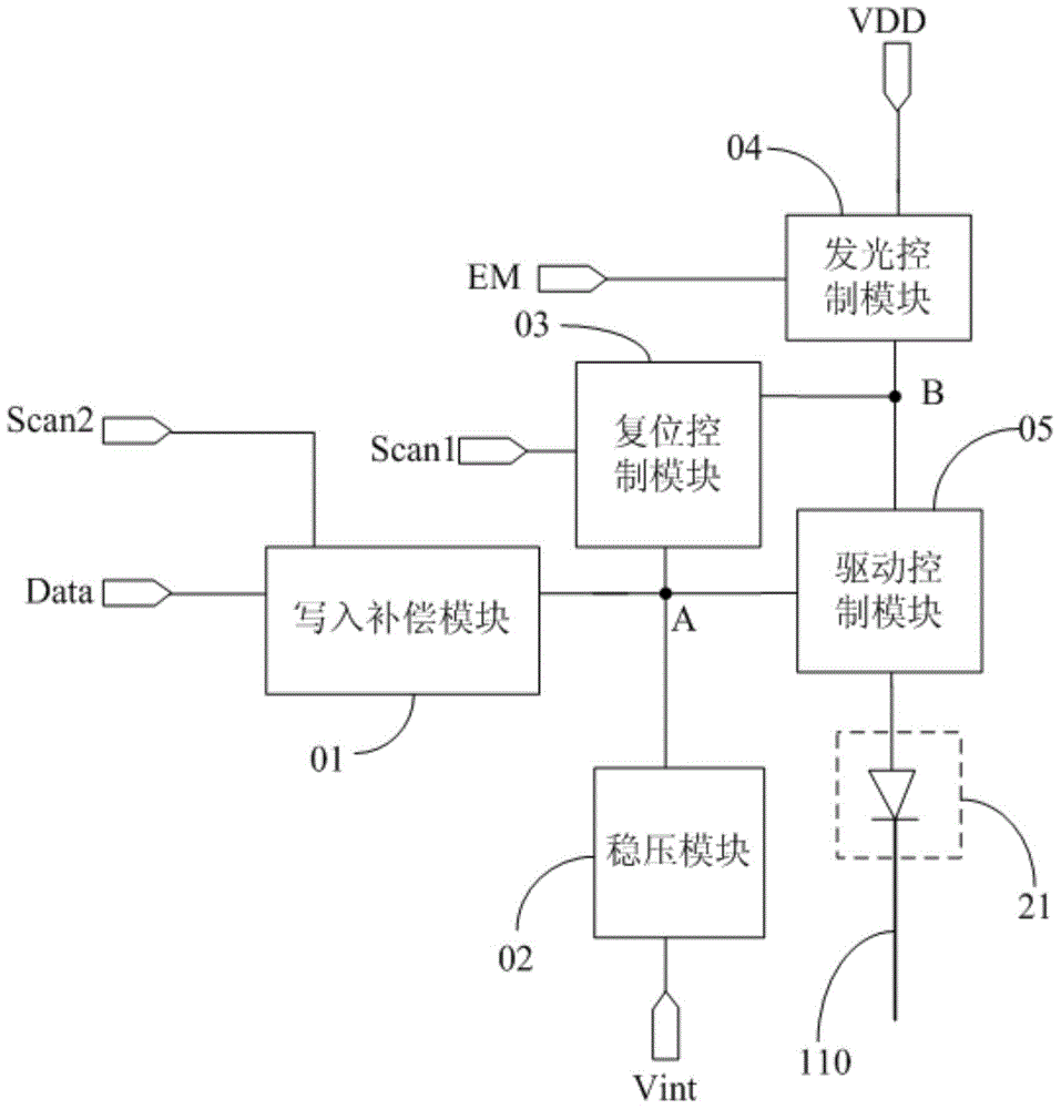
[0097] Such as Figure 5a As shown, the second switching transistor T2 and the third switching transistor T3 are in the on state, the first switching transistor T1, the first driving transistor DT1 and the second driving transistor DT2 are in the off state; the first reference of the first reference signal terminal VDD The signal is transmitted to the second node B through the turned-on third switching transistor T3, so that the potential of the second node B is the potential V of the first reference signal dd , the signal at the second node B is transmitted to the first node A through the turned-on second switching transistor T2, so the potential of the first node A is also the potential V of the first reference signal dd , the potential of the second reference signal terminal Vint is the potential V of the second reference signal ss , the capacitor C1 begins to charge.

[0098] In the second ph...

Embodiment 2

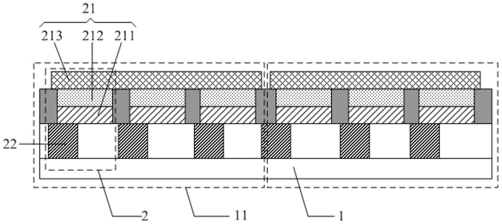
[0129] Take a sub-pixel as an example, such as Figure 8 As shown, the array substrate 1 sequentially includes a buffer layer 221, an active layer 222, a gate insulating layer 223, a gate 224, an interlayer insulating layer 225, a source electrode 226, a drain electrode 227, and a wire 110 arranged on the same layer. layer 228, the anode layer 211 and the cathode connection part 214, the light emitting layer 212, the sub-pixel defining layer 215 surrounding the light emitting layer 212, and the cathode layer 213.

[0130] Wherein, the cathode layer 213 is connected to the cathode connection part 214 through the via hole penetrating the sub-pixel defining layer 215, the anode layer 211 is connected to the drain electrode 227 through the via hole penetrating the planarization layer 228, and the cathode connection part 214 is connected to the drain electrode 227 through the The via hole is connected to the wire 110, the source electrode 226 and the drain electrode 227 are respect...


PUM


Abstract

The invention discloses an embedded touch display screen, a driving method thereof and a display device. At least two sub-pixels serve as a sub-pixel group, cathode layers of different sub-pixel groups are independent of one another, in other words, a cathode layer arranged on a whole surface is segmented in the prior art, the cathode layers of the sub-pixel groups are connected with a driver chip through wires, the cathode layers are reused as self-capacitance touch control electrodes, the driver chip detects capacitance value changes of the cathode layers through the wires so as to judge touch control positions, and therefore the touch control function is achieved. In the touch display screen, identical touch control scanning signals are superposed on signals output to signal ends of a sub-pixel circuit and the cathode layers by the driver chip in the fourth stage on the basis of signals output in the third stage, working states of modules of the sub-pixel circuit can be the same as the working state in the third stage, normal display can be guaranteed, and the embedded touch display screen based on an organic electroluminescent display screen is obtained.

Description

technical field [0001] The invention relates to the technical field of touch display, in particular to an embedded touch display screen, a driving method thereof and a display device. Background technique [0002] With the rapid development of display technology, touch screen panels (Touch Screen Panels) have gradually spread in people's lives. Currently, touch panels can be classified into: Add on Mode Touch Panel, On Cell Touch Panel, and In Cell Touch Panel according to their composition and structure. Among them, the plug-in touch screen is produced separately from the touch screen and the display screen, and then bonded together to form a display screen with touch function. The plug-in touch screen has disadvantages such as high production cost, low light transmittance, and thick modules. The embedded touch screen embeds the touch electrodes of the touch screen inside the display screen, which can reduce the overall thickness of the module and greatly reduce the produc...

Claims


Application Information

Patent Timeline
Patent Type & Authority Applications(China)
IPC IPC(8): G06F3/041G09G3/32
CPCG09G3/3233G09G2300/0814G09G2300/0819G09G2300/0842G09G2310/08G06F3/0412G06F3/044G09G2310/0251G06F3/04184H10K59/40G06F3/04166H10K59/129G09G3/3258G09G3/3291G09G2300/0426G09G2320/0646
Inventor 杨盛际董学薛海林王海生陈小川刘红娟孙拓马利飞孙文许睿王磊
Owner BOE TECH GRP CO LTD
Learn More