Variable inlet cross-section oil-gas separator

A technology of oil-gas separator and inlet cross-section, which is applied in the direction of machines/engines, crankcase ventilation, mechanical equipment, etc. It can solve the problems of poor separation effect of the separator, influence of separation efficiency, and uncompact structure, etc., and achieve high oil-gas separation efficiency, Simple structure, cost-effective effect

Inactive Publication Date: 2015-09-02
JILIN UNIV
View PDF7 Cites 3 Cited by
  • Summary
  • Abstract
  • Description
  • Claims
  • Application Information

AI Technical Summary

Problems solved by technology

The pressure loss of the labyrinth oil-gas separator is small, and the cost is low, but its structure is not compact, and it can only separate oil mist particles with a large particle size, and the separation efficiency is low
Although the cyclone oil-gas separator can separate smaller oil mist particles and obtain higher oil-gas separation efficiency, because it separates the oil droplets through the centrifugal force generated when the airflow rotates inside the separator, the overall separation efficiency is limited. The gas flow rate is seriously affected
Cyclone oil and gas separators for vehicles are usually structurally designed based on the corresponding blow-by gas volume under common working conditions, but this makes the separation effect of the separator poor at low blow-by gas volume, and the pressure loss is too high under high blow-by gas volume
The amount of blowby gas is not constant during the normal operation of the engine, so the above-mentioned inherent defects of the cyclone separator will restrict the best separation performance in the full range of engine operating conditions

Method used


Image

  • Variable inlet cross-section oil-gas separator
  • Variable inlet cross-section oil-gas separator
  • Variable inlet cross-section oil-gas separator

Examples


Embodiment Construction

[0020] The present invention will be described in detail below in combination with specific embodiments.

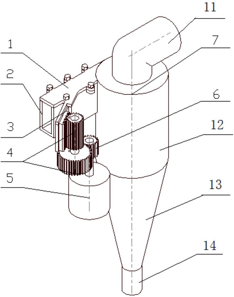
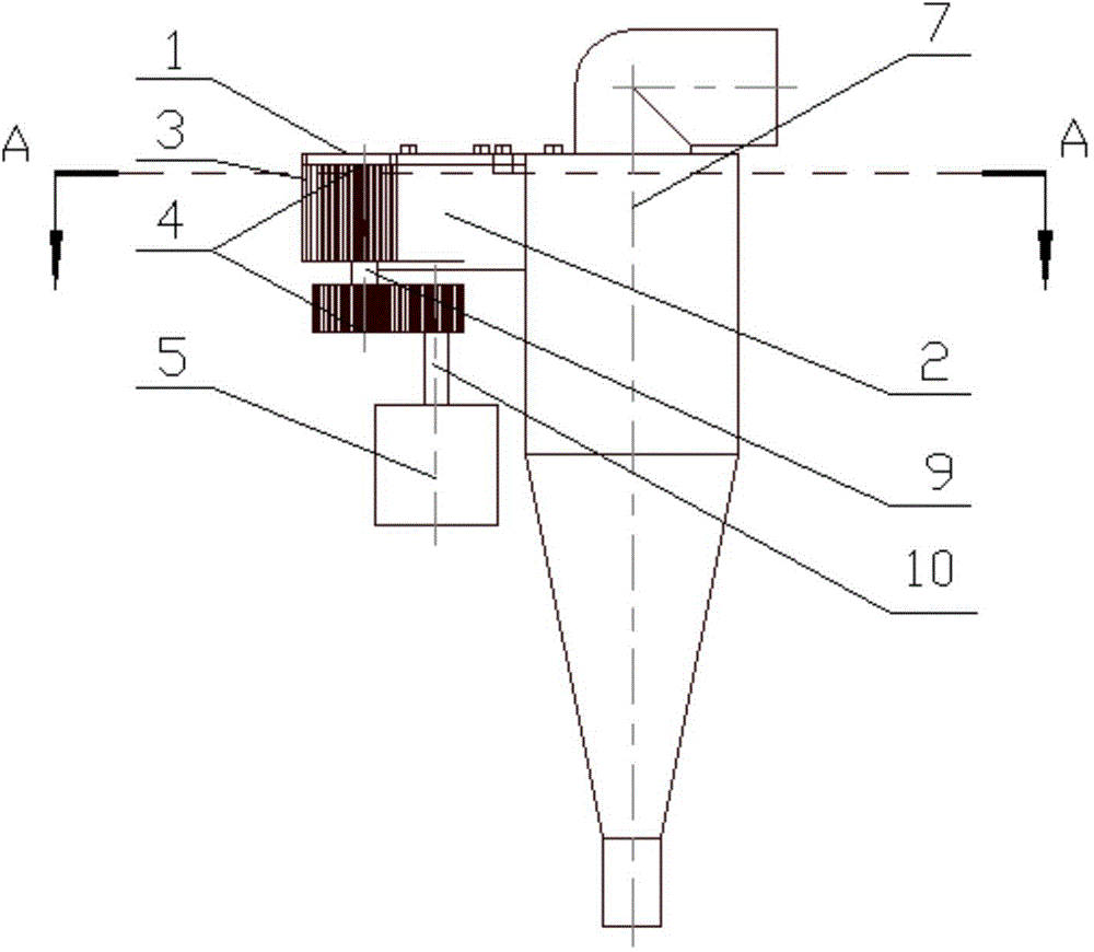
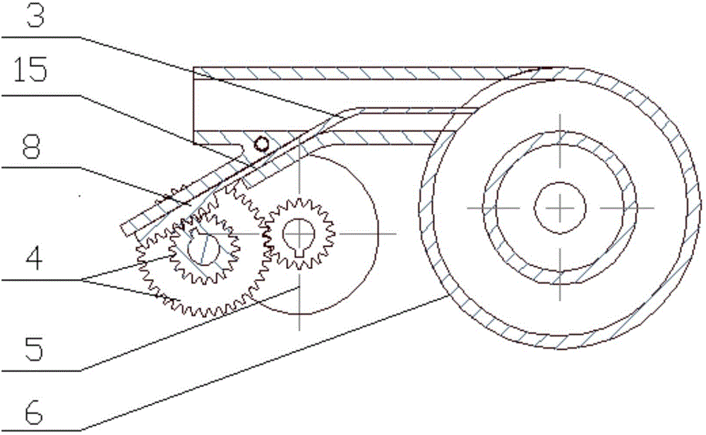
[0021] The invention provides a variable inlet section oil-gas separator, such as figure 1 As shown, it includes the main body 7 of the cyclone oil-gas separator, the intake pipe section 2 with guide grooves, the cover plate of the intake pipe section 1, the sliding plate 3, the reduction gear set 4, the stepping motor 5, and the main body of the cyclone oil-gas separator 7 Including air outlet 11, cylindrical section 12, conical section 13 and oil outlet 14 connected in sequence; stepper motor 5 is provided with stepper motor gear 6; reduction gear set 4 includes upper gear and lower gear connected by gear shaft 9 gears such as image 3 As shown, the end of the sliding piece 3 is a rack 8, the sliding piece 3 is installed in the guide groove 15 of the intake pipe section, and can slide in the intake pipe section 2 along the guide groove, the end of the rack meshes with ...


PUM


Abstract

The invention discloses a variable inlet cross-section oil-gas separator comprising a cyclone oil-gas separator body, a gas inlet pipe section with a guide slot, a gas inlet pipe section cover plate, a slip sheet, a reduction gear unit and a stepping motor. The cyclone oil-gas separator body comprises a gas outlet, a cylindrical section, a conical section and an oil outlet connected in sequence. A stepping motor gear is arranged on the stepping motor. The reduction gear unit comprises an upper gear and a lower gear connected through a gear shaft, a section of rack is arranged at the tail end of the slip sheet, the slip sheet is mounted in the guide slot of the gas inlet pipe section and can move in the gas inlet pipe section along the guide slot, the end of the rack is meshed with the upper gear, and the lower gear of the reduction gear unit is meshed with the stepping motor gear. According to the changes of working conditions of an engine, the position of the slip sheet in the gas inlet pipe section can be adjusted, air flow rate is controlled to further achieve satisfactory separation effect. The variable inlet cross-section oil-gas separator has the advantages of high separation effect and adaptability to gas leak amount changing with the working conditions.

Description

technical field [0001] The invention relates to a device for separating oil mist or solid particles in air flow, in particular to an oil-gas separator with variable inlet section. Background technique [0002] The increasingly stringent automobile emission regulations put forward higher requirements on the control of crankcase emissions. The current emission regulations stipulate that the gas escaped from the engine crankcase cannot be directly discharged into the atmosphere, but should be directed to the appropriate position of the intake system through the connecting pipe, and returned to the cylinder for re-combustion, that is, forced ventilation of the closed crankcase is adopted. However, the blow-by gas in the crankcase contains oil mist. If it is not treated effectively, the oil will adhere to the supercharger blades of the intake system, the wall of the intercooler, the wall of the intake valve, and the secret nozzle of the fuel injector along the way. Affect the wo...

Claims


Application Information

Patent Timeline
Patent Type & Authority Applications(China)
IPC IPC(8): F01M13/04
Inventor 曲大为崔凯程李君刘宇范鲁艳赵长庚苗志慧
Owner JILIN UNIV
Why Eureka
Try Eureka