
Camshaft and machining method thereof

A processing method and camshaft technology, applied to valve details, engine components, machines/engines, etc., can solve the problems of poor performance and reliability of diesel engines, mutual wear of cams and tappets, etc., to improve work reliability and improve The effect of improving service life and processing quality

Inactive Publication Date: 2015-09-02
GUANGXI YUCHAI MASCH CO LTD
View PDF7 Cites 2 Cited by
  • Summary
  • Abstract
  • Description
  • Claims
  • Application Information

AI Technical Summary

Problems solved by technology

[0006] The object of the present invention is to provide a kind of camshaft, thereby overcome the defect that the sharp edge of the camshaft in the prior art causes the cam and the tappet to wear each other, and the performance and reliability of the diesel engine are not good

Method used


Image

  • Camshaft and machining method thereof
  • Camshaft and machining method thereof
  • Camshaft and machining method thereof

Examples


Embodiment Construction

[0019] The specific embodiments of the present invention will be described in detail below in conjunction with the accompanying drawings, but it should be understood that the protection scope of the present invention is not limited by the specific embodiments.

[0020] Unless expressly stated otherwise, throughout the specification and claims, the term "comprise" or variations thereof such as "includes" or "includes" and the like will be understood to include the stated elements or constituents, and not Other elements or other components are not excluded.

[0021] Such as Figure 4 with 5 As shown, the camshaft 6 according to the specific embodiment of the present invention is provided with a thrust surface 61 , and in the installed state, the thrust surface 61 abuts against the body front end surface 1 of the body 3 . A plurality of cams 2 are arranged at intervals on the cam shaft 6 , and the position of each cam 2 corresponds to the position of the tappet 5 installed in t...


PUM


Abstract

The invention discloses a camshaft and a machining method thereof. A thrust surface and multiple spaced cams are arranged on the camshaft. Each cam comprises a working portion and two auxiliary portions, the working portion is in contact with a tappet, the two auxiliary portions are symmetrically arranged on two sides of the working portion, the longitudinal section of each auxiliary portion is in the same shape as the working portion but scaled down, and the distance between each point at the edge of the end face of each auxiliary portion and the axis of the camshaft is smaller than that between the corresponding point on the outer surface of the working portion and the axis of the camshaft. The cross section of each cam is high in middle and low in both ends, sharp edges are avoided existing on two sides of the cams to cause mutual wear of the cams and the tappets, meanwhile grinding wheels must be positioned relative to the thrust surface in the process of grinding the cams so as to ensure eccentricity of the cams and the tappets due to the structure, machining quality of the camshaft is improved, the cams on the same camshaft are similar in wear degree, and service lives of the camshaft and the tappets are prolonged.

Description

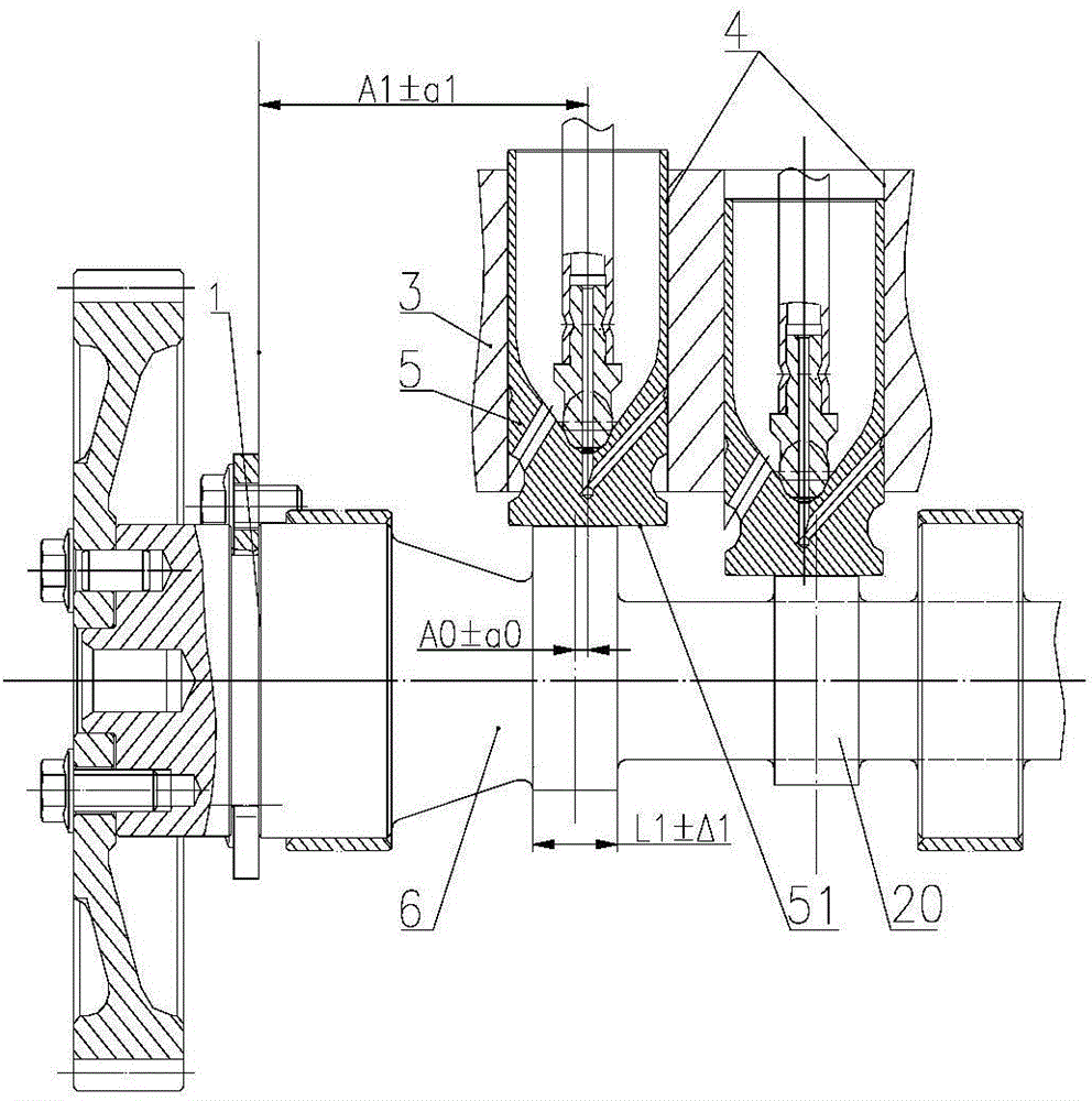
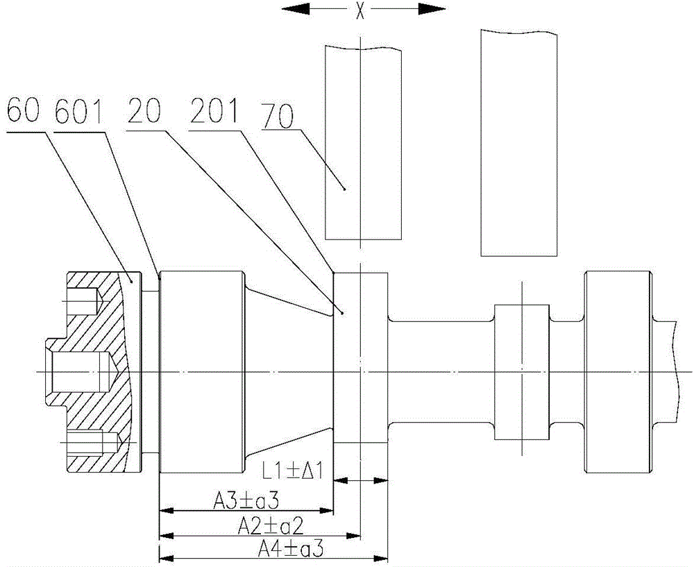
technical field [0001] The invention relates to the field of engines, in particular to a camshaft and a processing method thereof. Background technique [0002] Such as figure 1 with 2 In the installed state of the diesel engine camshaft in the prior art, the front end surface 1 of the machine body abuts against the thrust surface 601 of the camshaft 60 . Taking the cam 20 close to the front end surface 1 of the body as an example, the edges on both sides of the cam 20 of the camshaft 60 are sharp edges 201. Although the burrs on the sharp edges on both sides of the cam need to be removed after grinding, it is difficult to remove the burrs , and the efficiency is low. [0003] The working surface 51 contacted with the cam on the tappet 5 is a smooth surface, but because the two sides of the cam are sharp edges, and the cam is of irregular shape in the circumferential direction, in the actual working process, under the force of the tappet, the cam The sharp edges on both ...

Claims


Application Information

Patent Timeline
Patent Type & Authority Applications(China)
IPC IPC(8): F01L1/047F01L1/08B23P15/14
Inventor 刘振锋覃文王倩廖乾畅
Owner GUANGXI YUCHAI MASCH CO LTD
Learn More