System and method for low-cost and efficient separation and obtaining of single cell
A technology for separation and acquisition of single cells, applied in the fields of biotechnology and instrument science, which can solve the problems of uncontrollable separation and acquisition of single cells, high price, and low separation throughput, and achieve low cost, short time-consuming, and scalability strong effect
- Summary
- Abstract
- Description
- Claims
- Application Information
AI Technical Summary
Problems solved by technology
Method used
Image
Examples
Embodiment 1
[0039] Example 1: Low-cost and high-efficiency separation and acquisition of single cells based on routine laboratory imaging techniques
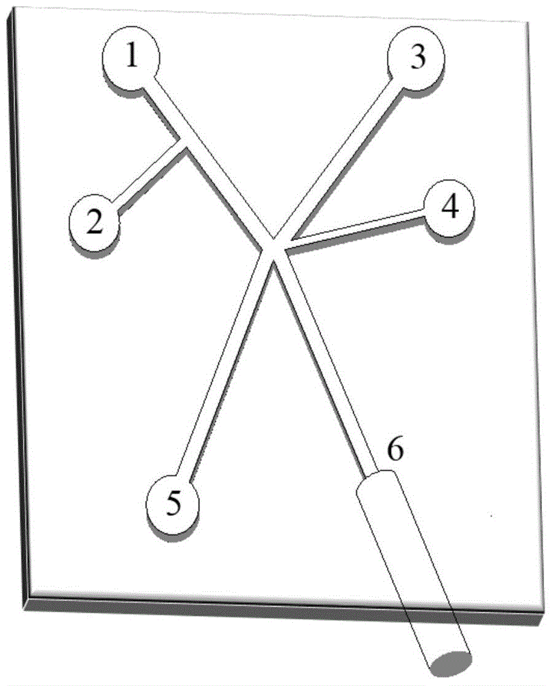
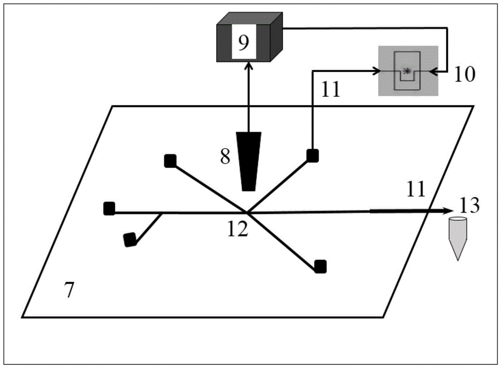
[0040] Such as figure 1 , 2 As shown, the low-cost and high-efficiency system for separating and obtaining single cells based on conventional laboratory imaging technology constructed in this example, the structure of the microfluidic chip 7 is shown in figure 1 , which includes: 1. Continuous oil phase inlet; 2. Cell suspension inlet; 3. Side flow oil phase inlet; 4. Electromagnetic valve connection port; 5. Waste liquid outlet; 6. Sorted droplet outlet. The microfluidic chip 7 is formed by bonding the upper layer of PDMS and the lower layer of glass substrate, wherein the upper layer has a 25-150 micron wide and 40-60 micron deep microchannel network obtained by wet etching, and the lower glass substrate is attached with a A layer of PDMS with a thickness of about 1 mm is used to easily produce water-in-oil droplets and bond seals betwe...
Embodiment 2
[0041] Example 2: Efficient separation and acquisition of single cells based on high-speed camera and image processing technology
[0042] Such as figure 1 , 2 As shown, the system constructed in this example is based on a high-speed camera and image processing method to efficiently separate and obtain single cells. The structure of the microfluidic chip 7 is shown in figure 1, which includes: 1. Continuous oil phase inlet; 2. Cell suspension inlet; 3. Side flow oil phase inlet; 4. Electromagnetic valve connection port; 5. Waste liquid outlet; 6. Sorted droplet outlet. The microfluidic chip 7 is formed by bonding the upper layer of PDMS and the lower layer of glass substrate, wherein the upper layer has a 25-150 micron wide and 40-60 micron deep microchannel network obtained by wet etching, and the lower glass substrate is attached with a A layer of PDMS with a thickness of about 1 mm is used to easily produce water-in-oil droplets and bond seals between the upper and lower ...
Embodiment 3
[0043] Example 3: Low-cost and efficient separation and acquisition of single cells based on fluorescence detection technology
[0044] Such as figure 1 , 2 As shown, the low-cost and high-efficiency separation and acquisition system based on fluorescence detection technology constructed in this example, the structure of the microfluidic chip 7 is shown in figure 1 , which includes: 1. Continuous oil phase inlet; 2. Cell suspension inlet; 3. Side flow oil phase inlet; 4. Electromagnetic valve connection port; 5. Waste liquid outlet; 6. Sorted droplet outlet. The microfluidic chip 7 is formed by bonding the upper layer of PDMS and the lower layer of glass substrate, wherein the upper layer has a 25-150 micron wide and 40-60 micron deep microchannel network obtained by wet etching, and the lower glass substrate is attached with a A layer of PDMS with a thickness of about 1 mm is used to easily produce water-in-oil droplets and bond seals between the upper and lower layers. Dr...
PUM
 Abstract
Description
Claims
Application Information
 - R&D
- Intellectual Property
- Life Sciences
- Materials
- Tech Scout
- Unparalleled Data Quality
- Higher Quality Content
- 60% Fewer Hallucinations
Browse by: Latest US Patents, China's latest patents, Technical Efficacy Thesaurus, Application Domain, Technology Topic, Popular Technical Reports.
© 2025 PatSnap. All rights reserved.Legal|Privacy policy|Modern Slavery Act Transparency Statement|Sitemap|About US| Contact US: help@patsnap.com


