
Hydraulic connecting bush, hydraulic connection, and hydraulic plug

A connecting sleeve and hydraulic technology, which is applied in the connection of packing seal with fluid pressure, sleeve/socket connection, pipe/pipe joint/pipe fitting, etc., can solve the problems of forgetting support ring, wrong assembly, easy failure, etc., to achieve The effect of cost saving, elimination of assembly errors, and reliable sealing effect

Active Publication Date: 2015-08-26
HITACHI ENERGY SWITZERLAND AG
View PDF9 Cites 2 Cited by
  • Summary
  • Abstract
  • Description
  • Claims
  • Application Information

AI Technical Summary

Problems solved by technology

However, it has proven to be disadvantageous that additional assembly effort is required for mounting the support ring
Another disadvantage is that the support ring can be forgotten or incorrectly assembled during assembly
Due to the disadvantages described, connecting sleeves with axially sealing sealing rings exhibit a certain vulnerability during assembly, which also results in the vulnerability of the connection during operation.
[0004] Similar disadvantages are also exhibited in prior art hydraulic plugs

Method used


Image

  • Hydraulic connecting bush, hydraulic connection, and hydraulic plug
  • Hydraulic connecting bush, hydraulic connection, and hydraulic plug
  • Hydraulic connecting bush, hydraulic connection, and hydraulic plug

Examples


Embodiment Construction

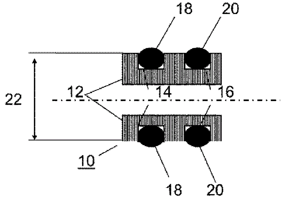
[0036] figure 1 A hydraulic connection sleeve 10 is shown which comprises a base body 12 which has at least two annular grooves 14 , 16 running around its outer cylindrical surface with sealing rings 18 , 20 inserted therein.

[0037] One possibility consists in designing the groove geometry according to the prior art. In the figures shown, the annular cross-sections of the sealing rings 18 , 20 protrude by way of example by 10-20% beyond the annular grooves 14 , 16 in order to ensure a minimum pre-compression in the installed state. However, it is also conceivable that the annular cross-sections of the sealing rings 18 , 20 protrude farther, for example to achieve a very high pre-compression. In order to create a uniform contact pressure of the sealing rings 18 , 20 it can be advantageous if all the sealing rings 18 , 20 protrude uniformly beyond the annular grooves 14 , 15 and are thus uniformly pre-compressed.

[0038] In the figures, the edges of the base body 12 are not...


PUM


Abstract

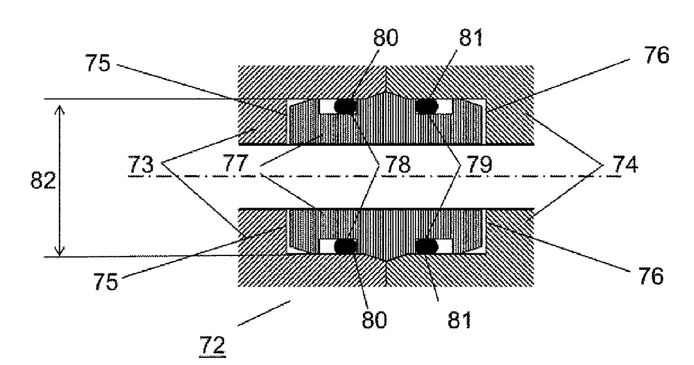
The invention relates to a hydraulic connecting bush (10) for connecting hydraulic lines (52, 54, 73, 74, 92, 94) for hydraulic circuit-breaker drives (98), comprising a hollow cylindrical main body (12, 60, 77) having at least two annular grooves (14, 16, 62, 64, 78, 79), which extend circumferentially on the outer cylindrical surface of the main body and have sealing rings (18, 20, 66, 68, 80, 81) inserted therein, wherein the main body (12, 60, 77) is made of a material having a first modulus of elasticity. The hydraulic connecting bush (10) is designed to be inserted in an overlapping manner in hydraulic lines (52, 54, 73, 74, 92, 94) to be connected that are in contact with each other at end faces of the hydraulic lines, the hydraulic lines being made of a material having a second modulus of elasticity, wherein a gap is formed between the main body (12, 60, 77) and the hydraulic lines (52, 54, 73, 74, 92, 94), such that, if the modulus of elasticity of the first material is less than the modulus of elasticity of the second material and an internal pressure is applied, the main body (12, 60, 77) is expanded more greatly than the hydraulic lines (52, 54, 73, 74, 92, 94) and thus the gap provided for technical reasons is closed in the region of the sealing rings. The invention further relates to a hydraulic connection (50, 72, 96), comprising an aforementioned hydraulic connecting bush (10). And the invention further relates to a hydraulic connecting plug (100, 120) for closing an open hydraulic line (102).

Description

technical field [0001] The invention relates to a hydraulic connection sleeve (Hydraulikverbindungsbuchse) for connecting a hydraulic line, for example for a hydraulic power switch drive (Leistungsschalterantrieb), which comprises at least two annular grooves running around its outer cylindrical surface (Mantelflaeche) A hollow cylindrical base body, an annular groove with a sealing ring inserted therein. Furthermore, the invention relates to a hydraulic connection comprising at least one first and a second hydraulic line for a power switch drive with a connection sleeve according to the invention, wherein the hydraulic line is connected by a material having a second modulus of elasticity material, and wherein the connecting sleeves are inserted one above the other into hydraulic lines whose ends abut one another. In addition, the invention relates to a hydraulic plug for closing an open hydraulic line, for example for a hydraulic power switch drive, comprising a hollow cylin...

Claims


Application Information

Patent Timeline
IPC IPC(8): F16L17/06F16L55/11
CPCF16L55/1141F16L17/06F16L21/002F16L21/022
Inventor M.施密特J.博伦德
Owner HITACHI ENERGY SWITZERLAND AG
Learn More