Industrial furnace
A kiln and industrial technology, applied in the field of industrial heating equipment, can solve the problems of uneven heating, uneven heat treatment of workpieces, poor mechanical effect, etc., and achieve the effects of good heat treatment effect, uniform heating and quality improvement.
- Summary
- Abstract
- Description
- Claims
- Application Information
AI Technical Summary
Problems solved by technology
Method used
Image

Examples
Embodiment 1
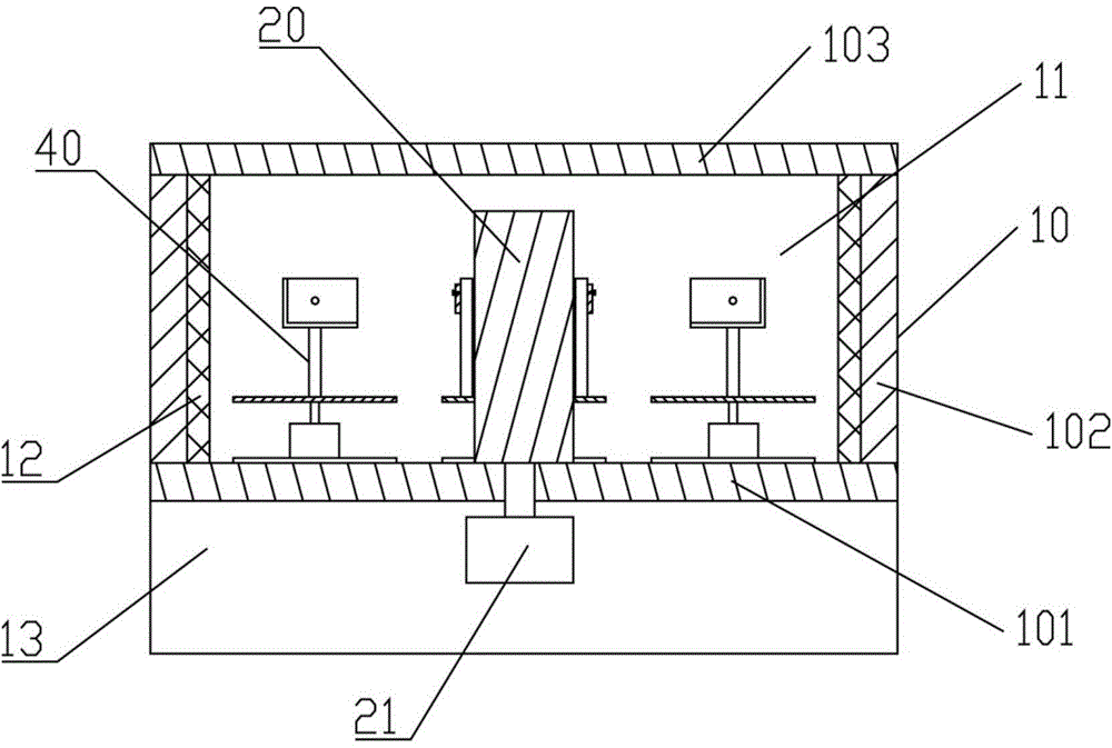
[0037] Reference Figure 1 to 3 As shown, the industrial furnace of the present invention includes: a furnace body 10, a heating device 20, a temperature control device 30, and a workpiece carrying device 40. The furnace body 10 is provided with a furnace 11. The furnace body 10 includes a bottom plate 101, a side wall 102 and an upper plate 103. The bottom plate 101 and the upper plate 103 are arranged at intervals. The side wall 102 is connected between the bottom plate 101 and the upper plate 103 to form an interior It has a cylindrical structure with a cavity, and the inner cavity of the furnace body 10 serves as the furnace 11. The inner wall of the furnace body 10 is also provided with a thermal insulation layer 12, which has a thermal insulation effect on the furnace, reduces the energy consumption of the heating device 20, and saves energy. The heating device 20 is arranged in the center of the furnace 11 for forming a temperature field for heating the workpiece in the ...
Embodiment 2
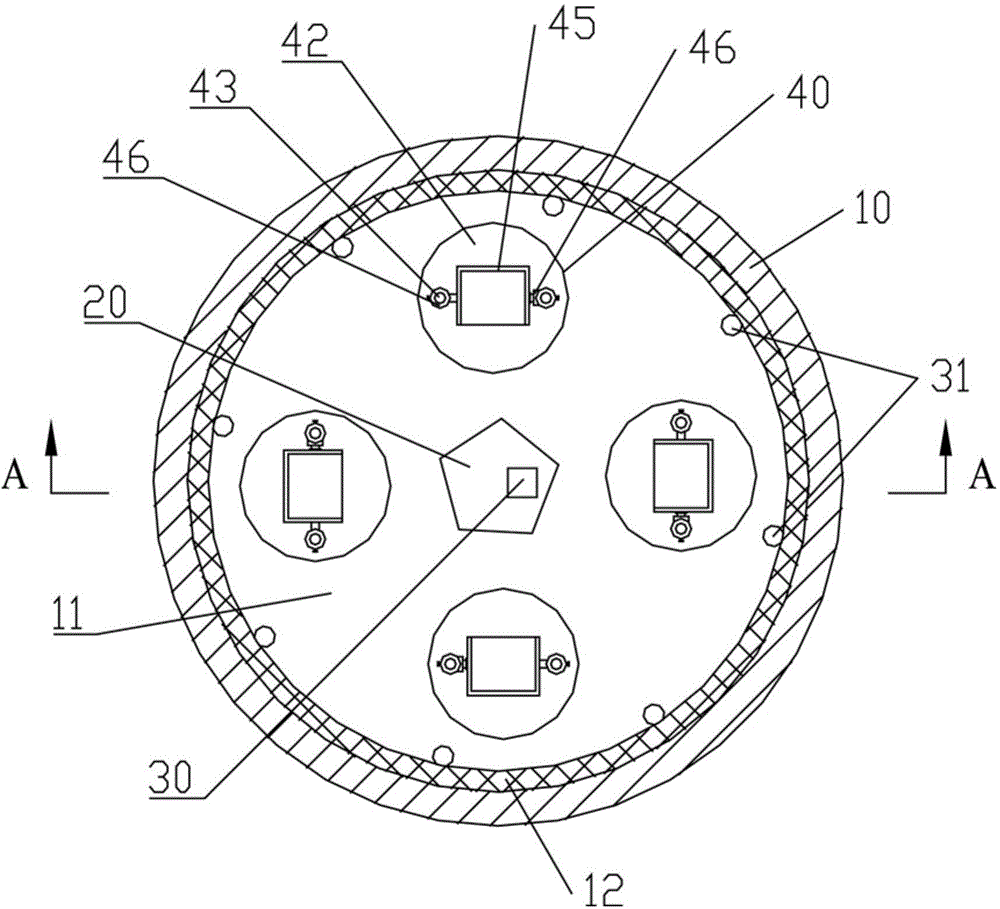
[0047] This embodiment is basically the same as embodiment 1, except that the reference Figure 4 As shown, there are multiple heating devices 20, four heating devices 20 are used in this embodiment, and the four heating devices 20 are evenly distributed in the furnace 11. Furthermore, each heating device 20 is connected to a heating rotary motor 21 to make the heating device 21 rotate around its center.
Embodiment 3
[0049] Reference Figure 5 with 6 As shown, the industrial furnace of the present invention includes: a furnace body 10, a heating device 20, a temperature control device 30, and a workpiece carrying device 50. The furnace body 10 is provided with a furnace 11. The furnace body 10 includes a bottom plate 101, a side wall 102 and an upper plate 103. The bottom plate 101 and the upper plate 103 are arranged at intervals. The side wall 102 is connected between the bottom plate 101 and the upper plate 103 to form an interior It has a cylindrical structure with a cavity, and the inner cavity serves as the furnace 11. The heating device 20 is arranged in the center of the furnace 11, the workpiece carrying device 50 includes a slide rail 51 and a pulley 52. The slide rail 51 is annularly arranged around the heating device 20. The pulley 52 is used to carry the workpiece, and the pulley 52 is slidably installed on the slide rail. At 51, the trolley 52 moves circularly around the hea...
PUM
 Abstract
Description
Claims
Application Information
 - R&D
- Intellectual Property
- Life Sciences
- Materials
- Tech Scout
- Unparalleled Data Quality
- Higher Quality Content
- 60% Fewer Hallucinations
Browse by: Latest US Patents, China's latest patents, Technical Efficacy Thesaurus, Application Domain, Technology Topic, Popular Technical Reports.
© 2025 PatSnap. All rights reserved.Legal|Privacy policy|Modern Slavery Act Transparency Statement|Sitemap|About US| Contact US: help@patsnap.com