
A combined light-cutting structure, led lamp and led lamp tube

A combined, LED light source technology, applied in the field of lighting, can solve problems such as high cost and limit the choice of manufacturers, and achieve the effects of suppressing glare, improving lighting comfort, and improving light output efficiency.

Active Publication Date: 2018-08-10
BEI JING DEEPCOOL SCI-TECH CO LTD
View PDF14 Cites 0 Cited by
  • Summary
  • Abstract
  • Description
  • Claims
  • Application Information

AI Technical Summary

Problems solved by technology

In this way, the cost of making the mold for the light source cavity is very high. If you need to adjust the direct light angle of the formed lamp in the later stage, you need to redevelop an expensive processing mold
[0003] In addition, the manufacturing process of the lamp panel limits the types of reflective materials used
For example, the stamping method is suitable for metal materials, the injection molding method is suitable for plastic materials, and the hot pressing method can only process a small number of polymer reflective materials imported from Japan. Therefore, the existing production methods of such lamps also greatly limit the manufacturers. Choice space on reflective material

Method used


Image

  • A combined light-cutting structure, led lamp and led lamp tube
  • A combined light-cutting structure, led lamp and led lamp tube
  • A combined light-cutting structure, led lamp and led lamp tube

Examples


Embodiment Construction

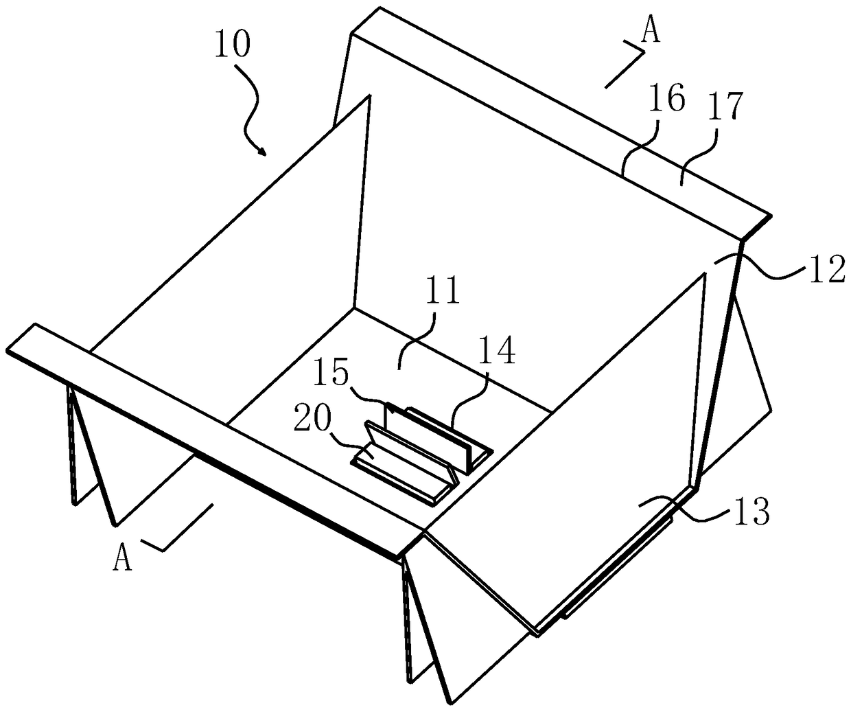
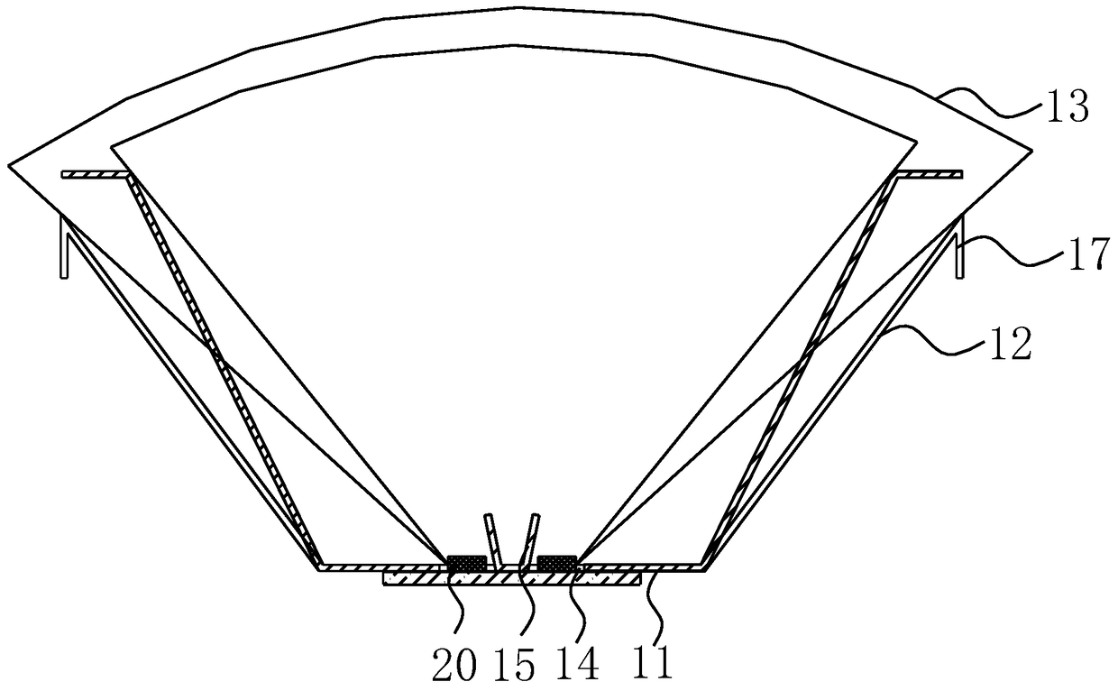
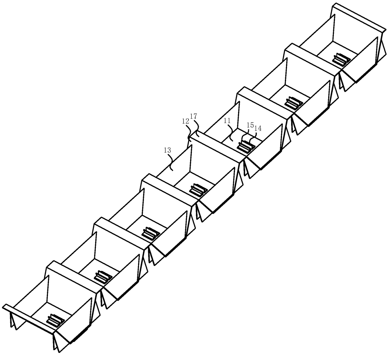
[0047] Such as figure 1 , 2 As shown, the combined light-cutting structure of this embodiment may generally include a light source cavity 10, the light source cavity 10 is composed of a bottom plate 11 and two holes respectively arranged on opposite sides of the bottom plate 11 for controlling the direct light angle of the LED light source. The side plate 12 and the partition plate 13 are formed; the side plate 12 and the partition plate 13 are in contact with each other through adjacent sides, and their bottom edges are respectively close to or attached to or directly connected with the bottom plate 11; the bottom plate 11 is provided with LED light source The exposed light source reserved hole 14 is obliquely provided with a shading baffle 15 on the side of the light source reserved hole 14, and the shading baffle 15 is used to further adjust the direct light emitted by the LED light source in the light source reserved hole 14. Angle; the area of ​​the shading baffle 15 is ...


PUM


Abstract

The invention provides a combined type light interception structure and an LED lamp and an LED lamp tube. The light interception structure comprises light source cavities formed by base plates, side plates and partition plates, and light source reserved holes which are used for exposing LED light sources are formed in the base plate; light blocking baffles are installed on the side edges of the light source reserved holes. According to the combined type light interception structure and the LED lamp and the LED lamp tube, the direct projection angles of the LED light sources can be controlled and adjusted by adjusting the inclination angles or heights or installation positions of the side plates, the partition plates and the light blocking baffles, and the light distribution curves of the light emitted from the light source cavities can meet lighting requirements of the specific environment. The invention further provides the LED lamp and the LED lamp tube which are equipped with the light interception structure, the angles of the light emitted from the LED lamp or the lamp tube are asymmetrical, the light angles can be adjusted according to use requirements, the influence on human eyes caused by direct radiation of the light sources can be restrained to the maximum extent, and the lighting comfort degree is improved.

Description

technical field [0001] The invention relates to the field of lighting, in particular to a combined light-cutting structure capable of adjusting the direct light angle of an LED light source, and an LED lamp and an LED lamp tube equipped with the light-cutting structure. Background technique [0002] When the LED light source is applied to the lamp, the application scheme of directly projecting light without passing through the soft light shade can be adopted. However, in order to suppress glare, control the beam angle and increase the light effect, the LED light source generally needs to be installed in a specific light source cavity. Under the existing technology, the LED light source can only be controlled by the fixed four walls of the light source cavity. There is no way to further adjust the direct angle of the LED light source for the light output angle. Existing LED lamps not only have one light source cavity, but also have an array shape in which multiple light sour...

Claims


Application Information

Patent Timeline
Patent Type & Authority Patents(China)
IPC IPC(8): F21V14/08F21K9/27F21K9/278F21V23/00F21Y115/10F21Y103/10
CPCF21S2/00F21V14/08F21V23/00
Inventor 赵党生
Owner BEI JING DEEPCOOL SCI-TECH CO LTD
Learn More