
Hydraulic orienting device for horizontal well

A technology of directional device and hydraulic jet, which is applied in wellbore/well components, production fluid, earthwork drilling and other directions, can solve the problem of inability to guarantee the accurate position of rotation, and achieve the effect of high construction efficiency, simple structure and ingenious installation.

Inactive Publication Date: 2015-08-26
CHINA UNIV OF PETROLEUM (BEIJING)
View PDF4 Cites 2 Cited by
  • Summary
  • Abstract
  • Description
  • Claims
  • Application Information

AI Technical Summary

Problems solved by technology

However, this method still uses the gravity of the gyro to provide the power to rotate. When the resistance in the well is large, it cannot be guaranteed to rotate to an accurate position.

Method used


Image

  • Hydraulic orienting device for horizontal well
  • Hydraulic orienting device for horizontal well
  • Hydraulic orienting device for horizontal well

Examples


Embodiment Construction

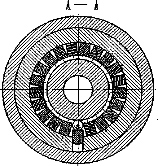
[0023] The interior of the horizontal well directional joint is composed of three units. They are core tube unit, shoe guide unit and orientation unit.

[0024] The core tube unit is mainly composed of the core tube 2 . Provides a channel for high pressure fluid flow. The core tube 2 has a groove at the lower end contact portion of the directional claw sleeve 8, and is connected by a directional screw 11, so that the directional claw sleeve can only move along the axis of the core tube 2. The inner diameter of the core pipe 2 is smaller than the lower joint 15, and there is a cavity between the lower joint 15 and the lower joint 15. When pumping high-pressure fluid into the well, due to the throttling effect of the nozzle, there will be high-pressure fluid in the cavity, and these high-pressure fluids will provide power for the forward and backward movement and rotation of the entire directional joint. There is an annular groove at the contact position between the core tube...


PUM


Abstract

The invention relates to a hydraulic orienting device for a horizontal well.The basic working principle is described in that a small steel ball with high density capable of freely rolling along a circumferential direction is arranged in the interior of a joint. With gravitational direction of the small ball constant, an indicate direction is provided for rotation of a perforating device under the well. When a high-pressure fluid is pumped into the shaft, joint rotation and orientation are finished at the same time. The orienting joint is capable of effectively positioning a complicated well bottom of the horizontal well with high reliability and has a simple structure and is easily prompted. The horizontal well does not have the problem of hydraulic oriented perforating. Therefore, the purpose of oriented perforating for oil reservoir is fulfilled.

Description

technical field [0001] The invention relates to the field of oil and gas exploitation, and is a novel horizontal well hydraulic directional tool. Background technique [0002] Perforation completion is a commonly used well completion method in oil and gas fields. Due to its large hole diameter and depth and no compaction zone on the hole wall, hydraulic sandblasting perforation is very effective for improving the perfection of production layers, especially low-permeability oil and gas reservoirs, and increasing the drainage area. For oil and gas wells containing water layers, it is generally necessary to avoid perforating near the water layer, so as to avoid the possibility that the blasthole may directly communicate with the water layer, causing the production well to break through the water in advance and "water flood" the oil layer, resulting in a decrease in production or even a shutdown. It is relatively easy to solve this problem in vertical wells, just determine the ...

Claims


Application Information

Patent Timeline
IPC IPC(8): E21B43/119E21B43/114
Inventor 黄中伟李根生牛继磊史怀忠周赫
Owner CHINA UNIV OF PETROLEUM (BEIJING)
Learn More