Symmetrical vapor deposition equipment reaction cavity

A technology of reaction chamber and vapor deposition, which is applied in the direction of gaseous chemical plating, metal material coating process, coating, etc., can solve the problems of reaction chamber pollution, unsophisticated design, increased floor space and cost, etc., to achieve The effect of improving uniformity and improving process quality

Active Publication Date: 2015-08-26
甘志银
View PDF4 Cites 10 Cited by
  • Summary
  • Abstract
  • Description
  • Claims
  • Application Information

AI Technical Summary

Problems solved by technology

[0003] The structure of the gas phase deposition equipment is complex, and the uniformity of the flow field inside the reaction chamber has an important influence on the uniformity and consistency of the process growth quality. In order to simplify the design of the gas phase equipment in the prior art, the tail gas extraction port is usually set on the side of the reaction chamber. Then install a uniform flow plate or a uniform flow tank in the reaction chamber to make the flow field in the reaction chamber uniform, because it is not easy to achieve the ultimate uniformity of the flow field in the reaction chamber when the vacuum pump pumping speed is high
In addition, the temperature of some vapor deposition processes is usually high, and the temperature of the exhaust gas is also high. The high-temperature exhaust gas may be deposited on the flowing wall surface to cause pollution of the reaction chamber. The high temperature of the exhaust gas will also cause damage to the subsequent exhaust gas treatment system or increase its design requirements. To increase the cost, the existing technology will set water cooling on the wall of the reaction chamber and / or specially design the cooling gas pipeline on the tail gas pipeline to cool the gas, cool the reaction gas and then discharge it
The design is not simple, while increasing the equipment space and cost

Method used


Image

  • Symmetrical vapor deposition equipment reaction cavity
  • Symmetrical vapor deposition equipment reaction cavity
  • Symmetrical vapor deposition equipment reaction cavity

Examples


Embodiment 1

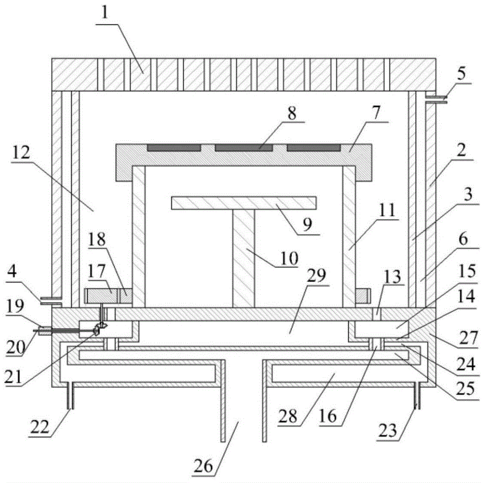
[0017] see figure 1 , the reaction chamber is provided with a reaction gas input body 1 and an exhaust gas outlet 26, and the exhaust gas outlet 26 is arranged at the center of the cavity base 27, in the reaction gas input body 1, the reaction gas channel 12, and the annular gas buffer chamber 15 1. The symmetrical position of the center of the air cavity 25, so as to maintain the symmetrical characteristics of the gas from entering to flowing out. A reaction gas channel 12 is provided in the reaction chamber, a chamber wall cooling chamber 6 is provided between the chamber shell 2 and the reaction chamber inner wall 3, and the chamber wall cooling chamber 6 is provided with a chamber wall cooling liquid inlet 4 and a chamber wall cooling liquid outlet 5 There is an annular gas buffer cavity 15 and an air cavity 25 in the middle of the cavity base 27. There is an annular gas buffer cavity 15 connected to the reaction gas flow channel 12 in the cavity base 27. The buffer cavity...

Embodiment 2

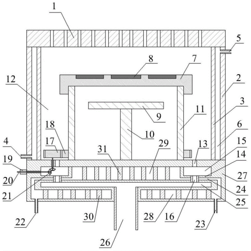
[0021] Same as Embodiment 1, the difference is that the cavity wall cooling cavity 6 , the cavity upper base cooling cavity 29 , and the lower base cooling cavity 28 are also provided with cooling liquid channel grooves along which the cooling liquid flows.

[0022] In the upper cooling chamber 29, a partition 31 is used to set a specific flow channel for the upper coolant, and the lower cooling chamber 28 is also provided with a partition 30 to form a specific flow channel, see figure 2 As shown, the flow of coolant in a specific channel can be controlled through the design of the partition, which can reduce the flow dead zone, enhance heat exchange, and further improve the cooling effect.

Embodiment 3

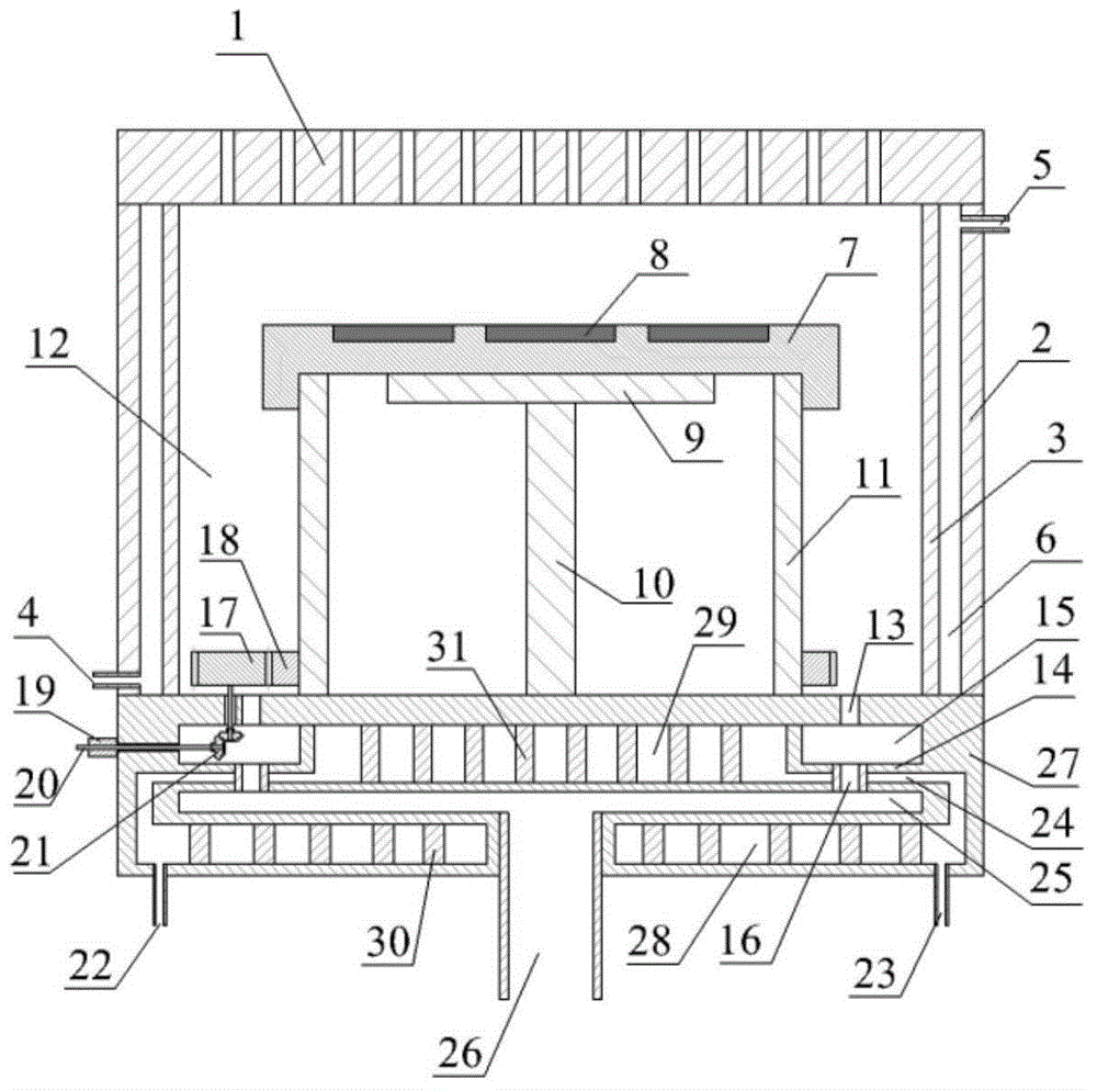
[0024] Same as Embodiment 1, the difference is that some organic molecule coating applications are not heated to generate physical and chemical reactions, but polymers in the gas are condensed and deposited on the substrate. At this time, the heater 9 can be a low-temperature constant temperature temperature control platform, see image 3 As shown, the slide tray 7 can directly and well contact the constant temperature temperature control platform, so that the constant temperature temperature console can control the slide tray 7 at the designed cooling temperature, which is beneficial to the deposition of organic molecules.


PUM


Abstract

The invention discloses a symmetrical vapor deposition equipment reaction cavity. The reaction cavity mainly comprises a gas input body, a heater, a slide carrying disc, a slide carrying disc support, a reaction cavity housing, a heater, a heater support, a reaction gas channel, a cavity pedestal and a tail gas outlet. The reaction cavity is characterized in that the tail gas outlet is arranged at the center of the cavity pedestal, a gas chamber is arranged in the middle of the cavity pedestal and a cooling chamber is arranged around the gas chamber. The tail gas outlet is arranged at the center of the cavity pedestal so that gas inlet and outlet symmetrical distribution is realized and uniformity of gas flowing distribution in the reaction cavity is guaranteed and improved. Tail gas goes through the gas chamber of the cavity pedestal and cooling surfaces of the gas chamber of the cavity pedestal cool the reaction tail gas so that the reaction tail gas is uniformly cooled, precipitates are reduced and tail gas treatment system damage caused by a high reaction tail gas temperature is avoided.

Description

technical field [0001] The invention relates to a chemical vapor deposition equipment, in particular to a symmetrical reaction chamber of the vapor deposition equipment. Background technique [0002] Vapor deposition technology is to use the physical and chemical processes that occur in the gas phase to form functional or decorative metal, non-metal or compound coatings on the surface of the workpiece. Vapor deposition equipment integrates precision machinery, semiconductor materials, vacuum electronics, fluid mechanics, optics, chemistry, and computer disciplines. It is a high-end semiconductor material and optoelectronic device manufacturing special equipment with high automation, high price and high technology integration. . [0003] The structure of the gas phase deposition equipment is complex, and the uniformity of the flow field inside the reaction chamber has an important influence on the uniformity and consistency of the process growth quality. In order to simplify...

Claims


Application Information

Patent Timeline
Patent Type & Authority Applications(China)
IPC IPC(8): C23C16/44C23C16/455
Inventor 甘志银植成杨
Owner 甘志银
Why Eureka
Try Eureka