Assembly, in particular internal combustion engine or compressor

A technology of compressors and internal combustion engines, which is applied in the direction of machines/engines, mechanical equipment, engine components, etc., can solve problems affecting the quietness of component operation, and achieve the effect of reducing quantity and economical production

Active Publication Date: 2015-08-19
赫伯特·许特林
View PDF7 Cites 4 Cited by
  • Summary
  • Abstract
  • Description
  • Claims
  • Application Information

AI Technical Summary

Problems solved by technology

Although functionally associated with a four-cylinder four-stroke cycle engine, however, a certain disadvantage is that this functional association is possible only because the control bend of the bending element is approximately sinusoidally formed
The sinusoidal shape of the control bend is disadvantageous, at least at higher rotational speeds, in that the guidance of the piston on the control bend is subject to A permanent change of direction corresponding to a sinusoidal shape, which leads to a "ski jumping effect" at least at high rotational speeds and can thus adversely affect the operating quietness of the components

Method used


Image

  • Assembly, in particular internal combustion engine or compressor
  • Assembly, in particular internal combustion engine or compressor
  • Assembly, in particular internal combustion engine or compressor

Examples


Embodiment Construction

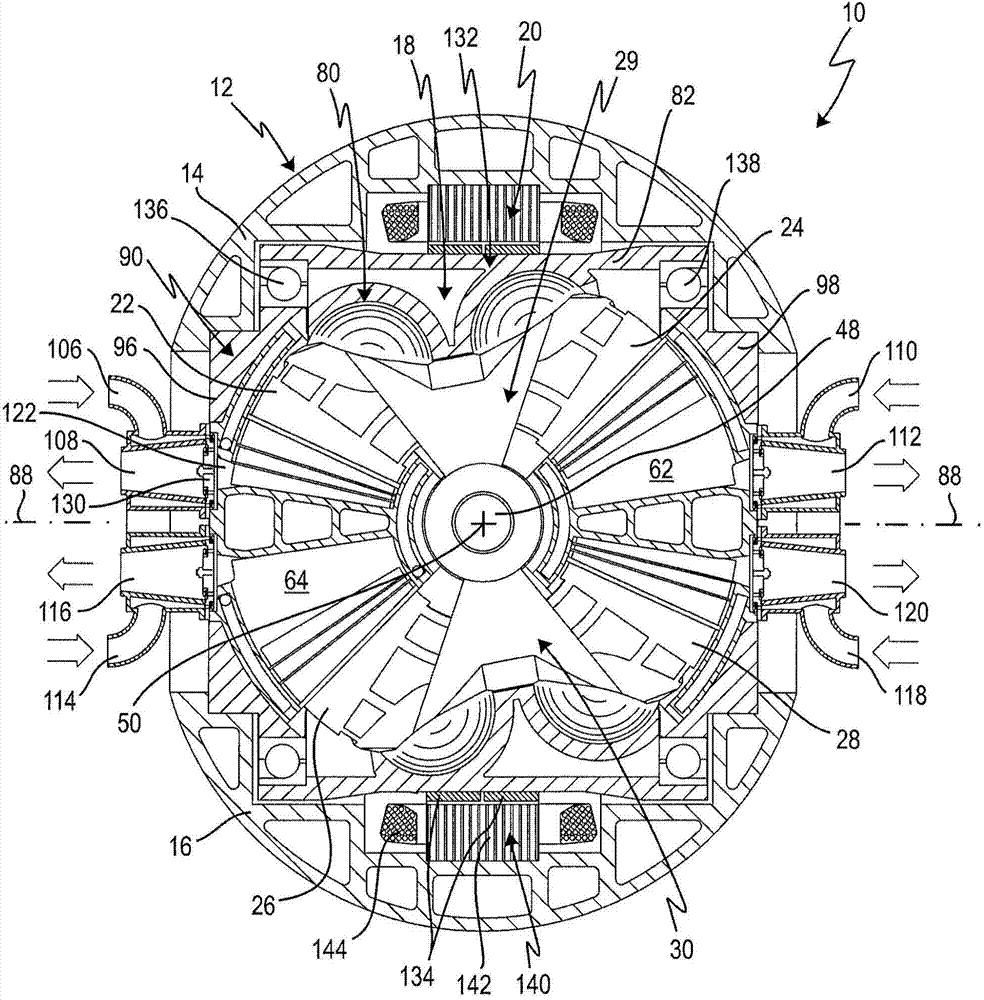
[0059] figure 1 Components are shown with the general reference numeral 10 . In the illustrated embodiment example, the assembly 10 is formed as a compressor with an integral electric motor component. However, with minor modifications, the assembly 10 can also be used as an internal combustion engine with an integrated electric motor component. However, use as a compressor is the preferred use.

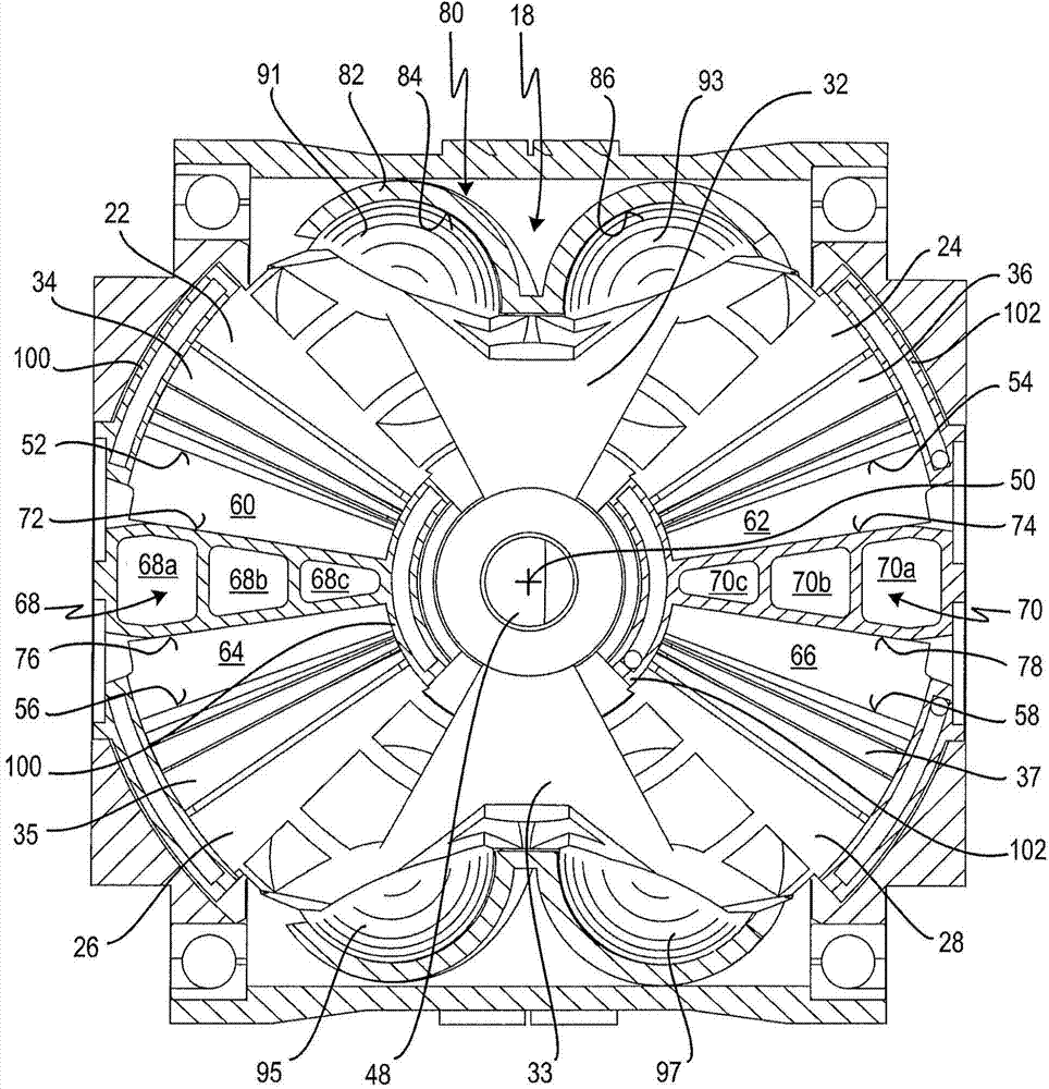
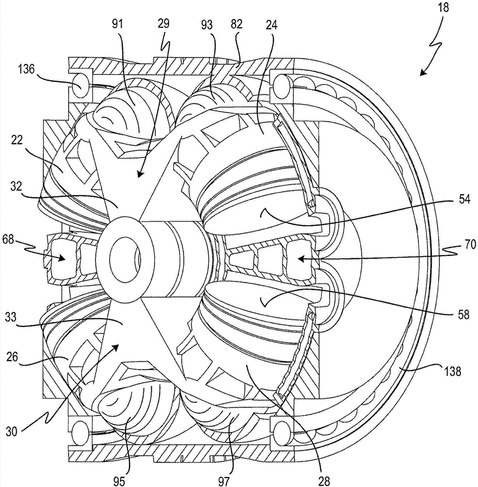
[0060] exist Figures 2 to 9 Additional details of assembly 10 are shown in . Figure 10 A slightly modified embodiment example of assembly 10 is shown.

[0061] refer to figure 1, the assembly 10 has a housing 12 which is essentially formed from two half-shells 14 and 16 . The two half-shells 14, 16 are fastened together via a number of bolts not shown.

[0062] Arranged within the housing 12 are a piston engine component 18 and an electric motor component 20 . First also refer to Figures 2 to 9 Piston engine component 18 is described in more detail.

[0063] The piston en...


PUM


Abstract

An assembly, in particular compressor or internal combustion engine, has a housing (12) in which there are arranged four pistons (22, 24, 26, 28) of which a first piston (22) has a first end surface (52), a second piston (24) has a second end surface (54), a third piston (26) has a third end surface (56) facing toward the first end surface (52), and a fourth piston (28) has a fourth end surface (58) facing toward the second end surface (54), wherein the pistons (22, 24, 26, 28) are pivotable in reciprocating fashion with limited stroke about a pivot axis (50); a piston cage (90) which is arranged in the housing (12) and in which the four pistons (22, 24, 26, 28) are arranged; a control mechanism (80) in the housing (12), which control mechanism has a cam element (82) on which the pistons (22, 24, 26, 28) are guided in order to generate the pivoting movements thereof, wherein the pistons are rotatable, together with the piston cage or the cam element (82), in the housing (12) about an axis of rotation (88) which is perpendicular to the pivot axis (50), wherein the cam element (82) is arranged radially outside the pistons (22, 24, 26, 28) and annularly around the axis of rotation (88); and working chambers (60; 62; 64; 66) in the housing (12) for in each case one working medium, said working chambers being formed between the end surfaces (52, 56 and 54, 58), which face toward one another, of the pistons (22, 24, 26, 28). Here, a first and a second working chamber (60, 62) are formed between the first end surface (52) of the first piston (22) and the third end surface (56) of the third piston (26), said first and second working chambers being sealingly separated from one another by a first partition (68), and a third and a fourth working chamber (64, 66) are formed between the second end surface (54) of the second piston (24) and the fourth end surface (58) of the fourth piston (28), said third and fourth working chambers being sealingly separated from one another by a second partition (70).

Description

technical field [0001] The invention relates to an assembly, in particular a compressor or an internal combustion engine, comprising a housing in which four pistons are arranged, a first piston of which has a first end face and a second piston has a second end face , the third piston has a third end face facing the first end face, and the fourth piston has a fourth end face facing the second end face, wherein the piston is pivotable around a pivot axis in stroke-limited reciprocating motion movement, the assembly also includes a piston cage, and the piston cage is arranged in the housing and the four pistons are arranged in the piston cage, the assembly also includes a control mechanism in the housing, the mechanism have a curved element on which the pistons are guided to produce their pivotal movement, wherein the pistons together with the piston cage can rotate in the housing about an axis of rotation perpendicular to the pivot axis, or a curved element rotatable in the hou...

Claims


Application Information

Patent Timeline
IPC IPC(8): F01C9/00F01C21/08F01C21/10
CPCF01C21/10F01C21/008F01C21/08F01C9/005
Inventor 赫伯特·许特林
Owner 赫伯特·许特林
Why Eureka
Try Eureka