Surface plasmon polariton directional coupler independent of polarization and control method thereof
A surface plasmon and directional coupler technology, applied in the field of nanophotonics
- Summary
- Abstract
- Description
- Claims
- Application Information
AI Technical Summary
Problems solved by technology
Method used
Image


Examples
Embodiment 1
[0032] As shown in Figure 1, the metal film of the present embodiment, small hole, ridge waveguide and protrusion nanoparticle; Wherein, the thickness of metal film is t, is provided with small hole on metal film; On metal film and is positioned at small hole Two ridge waveguides are arranged symmetrically at both ends, and the width of the ridge waveguide and the width of the small hole can be inconsistent. By adjusting the width w and height h of the ridge waveguide, the ridge waveguide only supports a single SPP mode; in the metal film Protruding nanoparticles are arranged on and on one side of the small hole; the protruding nanoparticles do not completely cover the edge of the small hole, forming a defective small hole structure.
[0033] First, a ridge waveguide is set on the metal film, w=290nm, h=300nm, and the metal film is made of gold film. The field distribution of the SPP mode supported by the ridge waveguide is shown in Figure 1(c). At this time, the incident ligh...
Embodiment 2
[0039] By tuning the structural parameters of the protruding nanoparticles, the p-polarized and s-polarized coupled SPP modes can be separated and propagate in opposite directions. In this example, the width of the protruding nanoparticles was reduced to 60 nm. The corresponding SEM images and details are shown in Figure 4 (a) shown. Other structural parameters of the defective pore structure are as follows: w=260nm, L=560nm, L d =240nm, h=350nm, and ΔL=60nm. The electric field CCD image obtained by the incident light λ=780nm is as follows Figure 4 (b) and (c) shown. It can be seen from the CCD image that the SPP mode coupled by the p-polarized incident light mainly propagates to the right along the ridge waveguide, and the corresponding extinction ratio is about (I R / I L ) p ≈5.1, so the right grating is illuminated as Figure 4 (b) shown. However, the SPP mode coupled by the s-polarized incident light mainly propagates to the left along the ridge waveguide, and t...
Embodiment 3
[0042] In this example, COMSOL Multiphysics is used to calculate the influence of the defective pinhole structure on the SPP mode coupling on the ridge waveguide. The calculation formula, the structural parameters of the ridge waveguide and the small hole are the results obtained from the experimental measurement of the sample shown in Figure 1, and the parameters are w=290nm, L=600nm, h=300nm, ΔL=60nm. Changing the structural parameter w of the protruding nanoparticles d and L d The strength of the obtained SPP mode is as Figure 5 (a) to (c) shown. It can be seen that the intensity of the SPP mode coupled by the incident light of p-polarization and s-polarization has different dependence on the structural parameters.
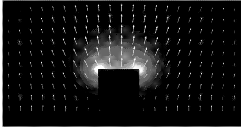
[0043] There is a sharp corner in the defective pinhole structure, as shown in Fig. 1(a), when the incident light is illuminated, charges tend to accumulate in these regions and form hot spots. For p-polarized incident light, there are three hot spots at t...
PUM
 Abstract
Description
Claims
Application Information
 - R&D
- Intellectual Property
- Life Sciences
- Materials
- Tech Scout
- Unparalleled Data Quality
- Higher Quality Content
- 60% Fewer Hallucinations
Browse by: Latest US Patents, China's latest patents, Technical Efficacy Thesaurus, Application Domain, Technology Topic, Popular Technical Reports.
© 2025 PatSnap. All rights reserved.Legal|Privacy policy|Modern Slavery Act Transparency Statement|Sitemap|About US| Contact US: help@patsnap.com